In this exercise, you will create a hide boundary on the surface, which will mask unwanted triangulation.
A boundary can be created from any polygon or polyline, but in this exercise you will use an existing breakline.
This exercise continues from Exercise 2: Deleting TIN Lines.
Add a hide boundary
- Open Surface-4C.dwg, which is located in the tutorials drawings folder. Note:
This drawing is similar to Surface-3.dwg with the addition of the C-TOPO-BRKL layer, which displays breaklines.
- In Toolspace, on the Prospector tab, under the Surfaces collection, expand the XGND surface.
- Under the XGND surface, expand the Definition collection. Right-click
 Boundaries. Click .
 - In the Add Boundaries dialog box, specify the following parameters:
- Name: XGND-Pond Hide
- Type: Hide
- Non-Destructive Breakline: Selected
- Mid-Ordinate Distance: 1.0000
- Click OK.
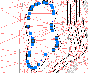
- In the drawing, select the polyline object that matches the perimeter of the pond.
The polyline that matches the pond perimeter

- Press Enter.
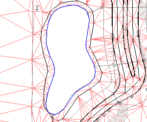
The hide boundary is added to the surface definition. The surface displayed in the drawing is modified to display the pond as a ‘hole’ in the surface.
How the surface should appear with the hide boundary

To continue this tutorial, go to Exercise 4: Smoothing a Surface.