In this exercise, you will create survey data using the Survey Command Window.
The Survey Command Window is used to enter survey commands directly using Command line input or interactively using the menus.
This exercise continues from Exercise 2: Creating Survey Data Using the Traverse Editor.
Create a new survey database
- Open Survey-4C.dwg, which is located in the tutorials drawings folder.
- In Toolspace, on the Survey tab, right-click Survey Databases. Click New Local Survey Database.
- In the New Local Survey Database dialog box, for the name, enter Survey 4. Click OK.
- In Toolspace, on the Survey tab, right-click the database Survey 4. Click Edit Survey Database Settings.
- In the Survey Database Settings dialog box, under Survey Command Window, specify the following parameters:
- Ditto Feature: Yes
- Auto Point Numbering: No
- Start Point Numbering From: 1
- Point Course Echo: Yes
- Figure Course Echo: Yes
- Point Coordinate Echo: Yes
- Figure Coordinate Echo: Yes
- Command Echo: Yes
- Use Batch File: Yes
- Use Output File: Yes
- Click OK.
Create a survey network
- In Toolspace, on the Survey tab, expand the Survey 4 database. Right-click the Networks collection. Click New.
- In the Network dialog box, for Name, enter Survey Network 4.
- Click OK.
Enter survey data into the survey command window
- In Toolspace, on the Survey tab, right-click Survey Network 4. Click Survey Command Window.
- In the Survey Command Window, enter the following commands into the Command line.
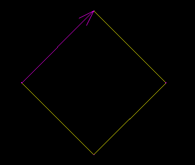
These are the survey language commands that will create four setups.
NE 1 1000.00 1000.00 “STA 1”
AZ 1 4 45.0000
STN 1
BS 4
AD 2 90.0000 100.00 “STA 2”
STN 2
BS 1
AD 3 90.0000 100.00 “STA 3”
STN 3
BS 2
AD 4 90.0000 100.00 “STA 4”
STN 4
BS 3
AD 1 90.0000 100.00
-
As you enter the commands, the top section of the Survey Command Window displays the resulting output and the bottom section echoes the input.
- Close the Survey Command Window.
- On the Survey tab, right-click Survey Network 4 and click Insert Into Drawing.
The new survey data is displayed in the drawing.
Click to see what the network should look like.

To continue this tutorial, go to Exercise 4: Calculating an Azimuth in The Astronomic Direction Calculator.