Specifying schema mapping values
You can set up schema mapping to associate attributes that have been defined in ArcGIS data to pipe and structure properties that are used in Civil 3D.
For example, if there is a field named Structure_Height in the dataset, you can map that to the Structure Height property in Civil 3D so that the height value assigned to the part is the same height value defined in ArcGIS.
To configure the schema mapping while bringing ArcGIS data into a drawing
After selecting pipe data to bring into a drawing, the Schema Mapping dialog box is displayed.
This dialog box will have a tab for each pipe or structure layer that you are bringing in to Civil 3D so you can define mapping parameters for each layer.
- Follow steps 1-11 in
To Bring ArcGIS Data into Civil 3D.
When you click Add to My Design Project, the Schema Mapping dialog box is displayed if you have chosen to create gravity pipes or structures in your drawing.
- For each
Civil Property Name, specify the
Source Property Name by clicking in the
Source Property Name field to show the drop-down list.
This list shows the attributes that were defined in the dataset. If there is not an equivalent attribute that matches the Civil Property Name, you can leave this field blank.
Note: A Civil Property Name that has an asterisk (*) after the name is required to have either a Source Property Name or a Default Value specified for it. - Specify the
Default Value to use for each property.
The first value found in the pipe network catalog is used as the default value. This value is used if a value for the specified Source Property Name cannot be found in the source data.
Note: It may be helpful to review the attributes that are set up in the dataset before or after bringing in the data so that you can see which attributes to map to Civil 3D properties and how to map attribute values. For more information, see To view attributes in ArcGIS. - Specify the
Source Unit to use for each numeric property. Click in the
Source Unit field to display a drop-down list of available unit types.
Note: The Civil Property Unit field is read-only and shows the units that are used in the current drawing (in/ft or mm/m).
- In the
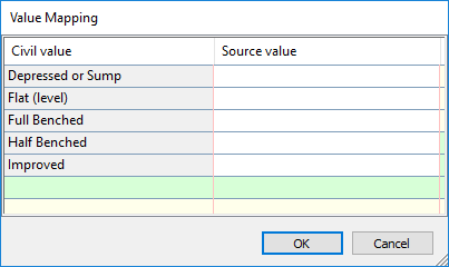
Value Mapping field, click
 to open the Value Mapping dialog box.

For each Civil Value listed, you can enter a Source Value that was assigned to the ArcGIS attribute. If the Source Value is found for a part in the source, the Civil Value will be applied to that part.
You can include multiple values by separating them with a semicolon: Manhole;Inlet;Outfall. Entries are not case-sensitive.

- Click OK to return to the Schema Mapping dialog box.
- Click
 to save the schema mapping to use for other pipes or structures.
- Click OK to continue.
You can check the Event Viewer for messages that occur during the import or pipe network schema mapping.
- The pipe network is named ArcGIS Network.
- The default styles specified in the CreateNetwork command settings are applied.
- A parts list named GenericPartList is created for the parts.
To configure the pipe network schema mapping after bringing ArcGIS data into a drawing
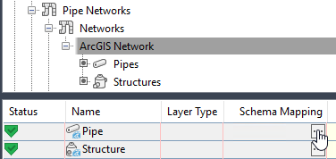
You can also access the Schema Mapping dialog box from within the Prospector item view.
Changes that you make to the schema mapping after the pipe network is created will be applied to the pipes and structures that are in the drawing.
- In Toolspace, on the Prospector tab, expand click the ArcGIS Network that was brought into the drawing using the Autodesk Connector for ArcGIS.
- In the Prospector item view, click
 in the Schema Mapping field of the item view to display the Schema Mapping dialog box.

- Follow steps 2- 8 in the procedure above.
To view attributes in ArcGIS
When you are bringing in gravity pipe network data, it may be helpful to review the attributes that are in the ArcGIS dataset before or after bringing in the data so that you can see which attributes to map to Civil 3D properties and how to map attribute values.
- Follow steps 1-11 in To Bring ArcGIS Data into Civil 3D.
- After selecting the feature type for each layer, click the Overview button
 in the Autodesk Connector for ArcGIS window.
- Under URL, click View Data Layer Source to open a web page with information about the dataset.
Note: You can also access this URL in the Data Source Manager dialog box after the data is brought into a Civil 3D drawing.
- To view the dataset in a map view, click the View In: ArcGIS.com Map link.
- In the ArcGIS map view, in the Details panel, click the Show Table icon
 for the layer.
The table view shows the attributes that are defined for the data and the attribute values that are specified.