To Place Factory Assets
Workflows for placing assets into a layout.
2D Factory layouts can be populated with associative factory assets. There are System Assets delivered with Factory Design; User Assets that you or someone else creates; and Cloud-based Assets that exist on a Cloud server and can be downloaded for use.
To place System Assets:
On the Factory tab, in the Tools panel, click Palettes, and then select Asset Browser
 from the drop-down menu. The browser that displays can be moved, docked, or left floating.
The browser has two view styles, Tree and Thumbnail. To change the view, at the top of the browser, click the down arrow on the Thumbnail/Tree Views buttons
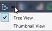 to expose the list and select the view style you want to use.
Double-click the System Assets folder to navigate to a particular asset.
Right-click the browser thumbnail image and click Preview on the pop-up context menu to see the asset in the Preview window.
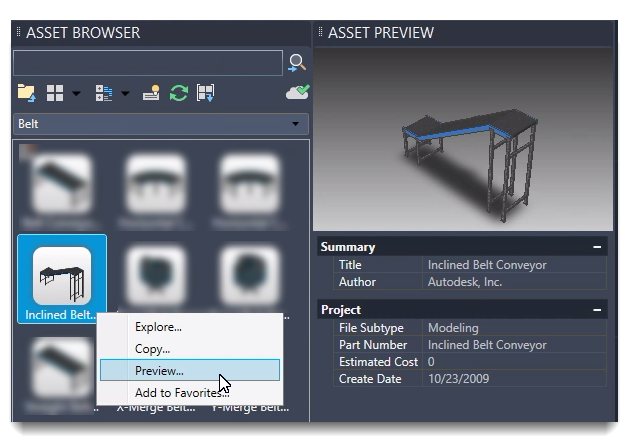
To place an asset, click and drag the asset from the browser into the layout.
The asset has a basepoint definition and is ready for you to specify that location in the layout. Click to place the asset.
Specify a rotation value, if needed. Otherwise, press Enter.
Continue to place copies of these assets or place other assets as needed.
Press Enter to end the input.
Cloud-based assets
When you drag a Cloud-based asset that has not been previously used and drop it onto your layout, a download message appears. To use the asset, accept the download option and the asset is downloaded into the folder for placement in your layout.
To place User Assets:
On the Factory tab, in the Tools panel, click Palettes, and then select Asset Browser from the drop-down menu.
Double-click the User Assets folder to navigate to a particular asset.
Any assets created with variations (called Asset Variants) in Inventor Factory appear with an icon similar to this at the upper left
 . The numeral indicates the number of variants available. Right-click over the asset to access the pop-up context menu. Then select the desired asset variant from the Factory > Asset Variant submenu.
Follow the same steps that are used to place System Assets. To specify whether the asset uses imperial or metric units, right-click the browser thumbnail image and click Explore. The Open dialog box presents the asset folder in the Factory Asset Library where you find Imperial and Metric folders having versions of the asset based on those unit types. Open the folder to select the asset using that unit system.
Note: We recommend authoring 3D assets in Inventor Factory. The authoring and publishing process includes a 2D asset publishing option, which creates and associates the 2D asset with the corresponding 3D asset. Once published using this option, the 2D asset appears in the AutoCAD Factory Asset Browser and is available for placement.
Placing a group of assets
The Insert asset group  command lets you copy a group of asset instances from within any Factory layout file and then reuse it in your current layout.
In the Asset Browser tool panel, select the Insert asset group
command.In the Insert Asset Group dialog, select the source layout file containing the group of asset instances you would like to place into your layout.
Click anywhere in your layout to place the group of assets. Only the asset instances and their relative positions are copied and the new asset instances are no longer associated with the group of assets in your original factory layout.
To place assets with connectors
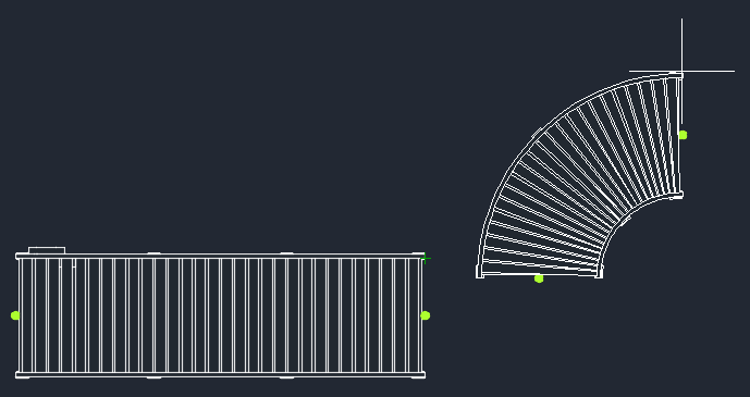
It is occasionally necessary to connect one asset to another in a linear fashion. This is often the case with conveyors, safety fencing, walls, and so on. Assets can be defined with one or more connectors in Inventor Factory and then connected together when placed in the AutoCAD Factory layout.
In the example shown below, a straight conveyor asset has been placed into the layout and a curved conveyor asset is being added. The green dots at the ends of each asset indicate the connector locations as defined in Inventor Factory.
Connecting assets is quick and easy. Simply move the asset to be connected so that its green connector dot is near the connector dot on the other asset. The two assets snap together as shown below.
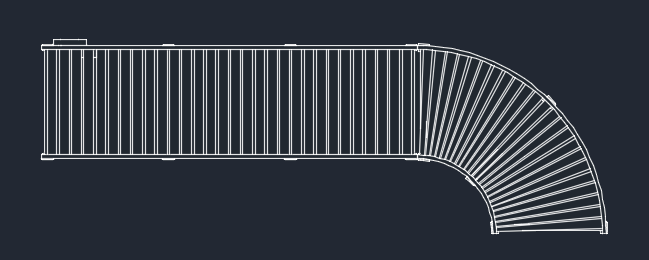
Connected assets move together as one component. If you wish to move them separately from one another, deactivate the Snap to Connector during placement and repositioning checkbox on the Factory Assets tab in the Options dialog.
For more information, see Factory Asset Options in the AutoCAD Factory help.