
Positional representations capture kinematic "snapshots" of assemblies to allow for motion studies and evaluation of an assembly in various positions. Positional representations are saved in the parent assembly. You can retrieve them at any time for further analysis or modification.
The Positional Representations folder is located in the Model and Representations browser. It is not available in the Mold Design browser.
Edits in the Mold environment are not allowed unless the assembly is closed and in the Primary positional representation.
What is the primary positional representation?
Each assembly has a positional representation named Primary that represents the default state of the assembly, where modeling operations take place. You cannot edit the Primary positional representation, but all new positional representations are copies of the primary. You change each as needed, and then reactivate the Primary positional representation to save the assembly. Edits in the Mold environment are allowed in the Primary or Closed positional representation.
The Primary representation is a "fail-safe" state. You can create many positional representations with various states of the assembly. You can lose track of assembly positions, visibility, constraint settings, and other values of the original assembly. No matter how many positional representations you create, you can always return to the default state of the assembly by making Primary the active representation.
How do I create and edit positional representations?
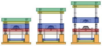
When you insert a new mold base, default positional representations are created. See these Help topics for details about positional representations.
What default representations does the mold application create?
When you insert a new mold base, system defined representations with named constraints are created. Significant named constraints for a two plate mold base are PL1 and Ejection. Significant named constraints for a three plate mold base are PL1, PL2, PL3, and Ejection. The value of these constraints is modified in system defined representations.
The following Positional Representations are created when you insert a new two plate mold base:
- Primary
- Product Open
- Ejection
- Close
- Free Drag
The following Positional Representations are created when you insert a new three plate mold base:
- Primary
- Runner Open
- Sprue Open
- Product Open
- Ejection
- Close
- Free Drag
Can I drive constraints in a positional representation?
Activate the Closed representation and then use Drive Constraint on the context menu in the Model browser. Specify a start and stop distance for a kinematic constraint to simulate mechanical motion. The Drive Constraint command is limited to one constraint, but you can drive additional constraints by using Equations to create algebraic relationships between constraints.
What are kinematic constraints?
A two plate mold base contains two kinematic constraints:
- PL1 Constraint between runner stripper plate (RSP) and cavity plate (AP).
- Ejection Constraint between ejector plate (EP) and the bottom clamp plate (BCP).
A three plate mold base contains four kinematic constraints:
- PL1 Constraint between core plate (BP) and cavity plate (AP).
- PL2 Constraint between runner stripper plate (RSP) and top clamping plate (TCP).
- PL3 Constraint between core plate (BP) and cavity plate (AP).
- Ejection Constraint between the ejector plate (EP) and bottom clamping plate (BCP).