Logical topologies connect features of any feature classes. The features need not be spatially connected, or have geometry. A logical topology can connect points with points or lines with lines or lines to points or attribute features with attribute features. For example, a logical topology can represent a waste water network or electrical transmission lines.
For each feature class that is part of a logical topology, a button is added to the feature class form. Use the Connection <topology name> button to open the connectivity system table <topology name>_CONN.
Flow Direction Management
When you define a logical topology, you specify a default flow direction that is valid for all features in the topology. For example, you set the default flow direction to Backward, and in AutoCAD Map 3D toolset you use the Manage Connections dialog box to set specific flow directions.
If the flow information is stored with the feature data, you can specify the feature class attribute that stores the flow direction along with the values that indicate the flow options. For example, if a road feature class uses the attribute DIRECTION to store the flow, use that attribute to define the flow direction.
Connection Tolerance Radius
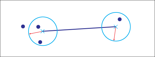
The connection tolerance radius determines when a feature is spatially connected to another feature. For example, when you digitize features using AutoCAD Map 3D toolset, the connection is created automatically if they lie within the tolerance.

During topology initialization, the connections of spatially connected features are automatically added to the connectivity table.
You can modify the connection tolerance radius. The radius uses the default length unit of the industry model. For example, if your coordinate system uses meters, the unit is meters.
If you modify the connection tolerance radius, you must initialize the topology again.
Utility Topologies
For a utility model, restrictions apply. Create the logical topology during the creation of the utility model. See also Data Model: Utility Model.
A network topology is a sub type of a logical topology that is based on an arc-node model and is based on geometry. Utility models are based on logical topologies that connect points and lines.
Utility applications, such as Water, Gas, or Wastewater, use logical topologies that comply with the utility model.
The data model component for utility networks requires a logical topology that is based on an arc-node model. During the creation of a utility model, you can create an appropriate logical topology.