Add roads to your map and create a composite style to combine two line styles to form a realistic-looking road style. The composite style is displayed when you zoom in to a certain scale range in your map. A simpler style is displayed when you zoom out.
To add roads to your map
- If you have not already done so, copy the tutorial sample files to your local drive.
- Open your finished map from the previous lesson.
- Click

 OpenDrawing.
- Locate build_map1.dwg.
- Select the map, and click Open.
- Click
- In the Task Pane, switch to Display Manager.
- Drag and drop the roads into Display Manager.
- Use File Explorer to navigate to the folder where you copied the sample files.
- Resize the AutoCAD Map 3D toolset window and the sample data folder window so you can see both of them at the same time.
- Drag and drop the Roads.shp file into the map area.
- In Display Manager, select the Roads layer and click Style.
Note: If the Style Editor is docked, move your cursor over it to display it. It might be docked at the left side of the application window.
- In the Style Editor, click the Style field.
- In the Style Line dialog box, click Add Symbol.
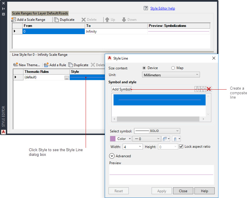
Use Add Symbol to combine line styles.
- Do the following:
- Change Unit to Millimeters.
- Change the line thickness to 2.
- Change the Color to black (if it is not black already).
This is the bottom line of the composite style.
- Create the second part of the line style.
- Select the top line in the Symbol And Style area.
- For Select Symbol, choose a dashed line pattern.
- Leave the line color set to yellow (or change it to yellow if it is a different color)
Notice that the preview now displays a dark line with a dashed yellow line inside it.
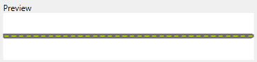
A composite line for roads
- Click Apply and then click Close.
Now define scale ranges and assign styles to them. Each scale range represents the zoom levels at which a style is displayed. When you are zoomed between the levels of a range, the style for that range is displayed.
- In the Scale Ranges area at the top of the Style Editor, click the word “Infinity” and enter
30000 to replace it.
The composite style you created appears for this range.
- Define another scale range and specify a solid line style for it.
When the zoom level is within this range, the roads appear as solid lines.
- Click Add A Scale Range.
- Set the range to go from 30000 to 50000.
- Click the Style field in the bottom area of the Style Editor.
- Delete the top style (the dashed yellow line).
- Set the line weight for the remaining (black) line to 1.
- Click Apply and then click Close.
- Define another scale range so that no styling is applied to the roads when you zoom out to a distant view.
- Click Add A Scale Range again.
- Set the new range to go from 50000 to infinity.
- Click the Style field in the bottom area of the Style Editor.
- Change the line color to No Color.
- Click Apply and then click Close.
The style for this scale range is now blank. When you zoom out to a distant view, you cannot see the roads.
- Close the Style Editor and save the file.
To continue this tutorial, go to Exercise 2: View styles at different zoom levels.