Vector_Map TextureMap and MAXScript
Introduction
The Vector_Map TextureMap available in 3ds Max 2014 and higher provides support for scalable vector graphics file formats including the standard SVG XML open standard developed by the World Wide Web Consortium. It also supports compressed SVG in .SVGZ format, Adobe Illustrator .AI files, Adobe Portable Document Format (.PDF) files and Autodesk AutoCAD Pattern (.PAT) files.
In addition to the exposure of the Vector_Map TextureMap object to MAXScript documented here, the 3ds Max implementation provides exclusive support for MAXScript functions and expressions inside the actual SVG XML file, allowing for a much tighter integration of vector graphics with the actual scene content. This includes the creation of dynamic vector graphics reacting the scene animation or depending on scene objects properties, text rendering and much more.
This topic discusses the creation of SVG files using MAXScript, the inclusion of MAXScript commands inside the SVG XML source files, and provides some examples demonstrating the power of this feature.
Writing SVG Files
Basic Format Structure
The SVG file is a XML text file. Its content is enclosed in <svg> tags, which identifies the content as Scalable Vector Graphics definition.
Inside the body of the SVG file, one or more entities can be defined, including rectangles, circles, ellipses, lines, polylines, polygons, images and texts.
The outside color (stroke color) and inside color (fill color) can be defined as hexadecimal values. Patterns and Gradients can also be used instead of solid colors.
Various properties specific for each entity can be defined, otherwise they will be assumed to have default values.
Entities can be transformed and grouped for convenience.
SIMPLEST EXAMPLE:
   <svg  xmlns="http://www.w3.org/2000/svg"
         xmlns:xlink="http://www.w3.org/1999/xlink">
       <rect x="255" y="255" height="512" width="512"
             style="stroke:#ff8800; fill: #0000aa"/>
   </svg>
Save this code in a new text file under the name "Rectangle.svg" in your 3ds Max UserScripts folder.
Then create a Vector_Map TextureMap and load this code as the Vector File.
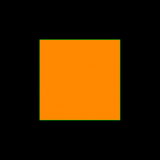
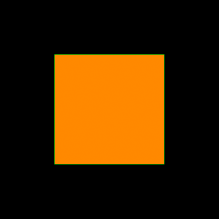
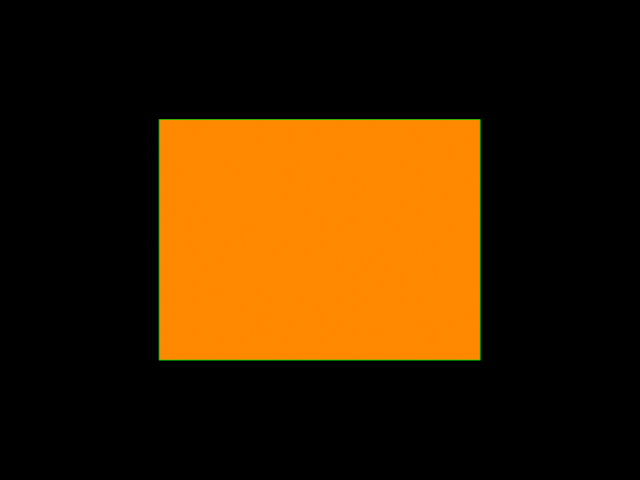
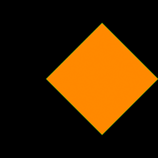
Then render the resulting map into bitmaps with different resolutions - 160x160, 320x320 and 640x320.
You can do this manually, or using MAXScript:
   theSVGMap = VectorMap()
   theSVGMap.vectorfile = GetDir #userscripts + "\\rectangle.svg"
   for i in #([160,160], [320,320], [640,480]) do
     display (renderMap theSVGMap size:i filter:true)
Evaluating the above MAXScript will render 3 images with different resolutions from the same scalable graphics definition.
Here are the resulting images:
Let's discuss the content of the SVG file to understand how it works.
The 3ds Max Vector_Map TextureMap assumes that the Canvas the graphics are drawn into is 1024x1024 units in size.
The origin [0,0] is the upper left corner, just like in MAXScript Bitmap values. The coordinate of the bottom right corner is [1023,1023]
Thus, when specifying the Position and Size of an entity, we have to assume that the center of the Canvas is at [511,511]. Specifying the upper left corner of the Rectangle at x=255 and y=255 and giving it a width and height of 512 units aligns it at the Canvas' center.
This Canvas size assumption is specific for 3ds Max and does not necessarily apply to SVG and other vector graphics files coming from other sources. That's why the Vector_Map provides Cropping controls to extract only a portion of the rasterized bitmap if the entities were defined in other coordinates.
Applying Transformations
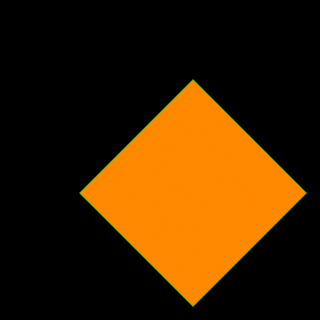
Let's rotate the rectangle that we created at 45 degrees about its center.
TRANSFORMATIONS EXAMPLE:
   <svg  xmlns="http://www.w3.org/2000/svg"
         xmlns:xlink="http://www.w3.org/1999/xlink">
       <rect x="255" y="255" height="512" width="512"
             style="stroke:#ff8800; fill: #0000aa"
             transform="rotate(45 511 511)" />
   </svg>
Re-save this code in the same text file under the name "Rectangle.svg" in your 3ds Max UserScripts folder.
Update the Vector_Map either manually in the Material Editor, or via MAXScript using
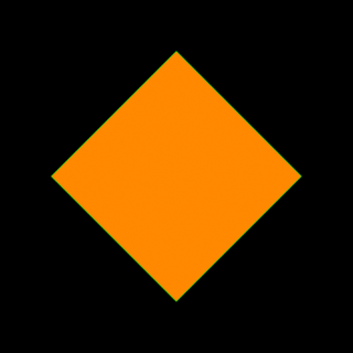
theSVGMap.reload()Render the resulting map into a bitmap with resolutions of 320x320.
   theSVGMap.reload()
   display (renderMap theSVGMap size:[320,320] filter:true)
Evaluating this script will render the scalable graphics definition and display the bitmap.
Here are the resulting image:
Let's also translate the shape 150 units along X before we have rotated it.
When multiple transformations are specified, each one modifies the current coordinate system in the given order:
   <svg  xmlns="http://www.w3.org/2000/svg"
         xmlns:xlink="http://www.w3.org/1999/xlink">
       <rect x="255" y="255" height="512" width="512"
             style="stroke:#ff8800; fill: #0000aa"
             transform="translate(150) rotate(45 511 511)" />
   </svg>
Saving the SVG definition and running the same MAXScript as above produces the following:
In the above case, the translation was applied before the rotation, so the coordinate system was first shifted to the right, then the rotation was performed.
If we were to specify the Translation after the rotation, the rotation will occur first, then the translation will occur in the already rotated coordinate system.
   <svg  xmlns="http://www.w3.org/2000/svg"
         xmlns:xlink="http://www.w3.org/1999/xlink">
       <rect x="255" y="255" height="512" width="512"
             style="stroke:#ff8800; fill: #0000aa"
             transform="rotate(45 511 511) translate(150)" />
   </svg>
In this case, the X axis is pointing at the bottom right corner, and the rectangle is shifted diagonally 150 units in that direction:
Creating Text
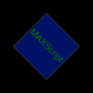
TEXT EXAMPLE:
   <svg  xmlns="http://www.w3.org/2000/svg"
     xmlns:xlink="http://www.w3.org/1999/xlink">
     <rect x="255" y="255" height="512" width="512"
       transform="rotate(45 511 511)"
       style="stroke:#ffff00; fill:#001166">
     </rect>
     <text x="255" y="255"
       transform="rotate(45 511 511) translate(15 280)"
       style="stroke:#000000; fill:#008800; font-size:100; font-family:Arial">
       MAXScript
     </text>
   </svg>
Save this code in a new text file under the name "RectangleText.svg" in your 3ds Max UserScripts folder.
Run the following MAXScript.
   theSVGMap = VectorMap()
   theSVGMap.vectorfile = GetDir #userscripts + "\\RectangleText.svg"
   display (renderMap theSVGMap size:[320,320] filter:true)
Evaluating this script will render the following image:
Defining Gradients, Stroke Width And Corner Radii
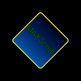
Instead of filling the shape with a solid color, we could define a named Gradient and use it in place of the color for the rectangle's fill: parameter.
This Gradient will have the id "LinearGradient" and will interpolate linearly along the Y axis from a dark blue color with zero opacity to a brighter blue color with full opacity.
In the Rectangle's definition, we will use the id "LinearGradient" to pass this definition to the fill: parameter.
We will also set the corner radii to 30 units and the stroke width of both the rectangle and the text to 3 units.
GRADIENT EXAMPLE:
   <svg  xmlns="http://www.w3.org/2000/svg"
     xmlns:xlink="http://www.w3.org/1999/xlink">
     <defs>
       <linearGradient id="LinearGradient1"
         x1="0%" y1="0%"
         x2="0%" y2="100%"
         spreadMethod="pad">
         <stop offset="0%"   stop-color="#001166" stop-opacity="0"/>
         <stop offset="100%" stop-color="#0055aa" stop-opacity="1"/>
       </linearGradient>
     </defs>
     <rect x="255" y="255" height="512" width="512" rx="30" ry="30"
       transform="rotate(45 511 511)"
       style="stroke:#ffff00; fill:url(#LinearGradient1); stroke-width: 10">
     </rect>
     <text x="255" y="255"
       transform="rotate(45 511 511) translate(15 280)"
       style="stroke:#000000; stroke-width:3; fill:#008800; font-size : 100; font-family:Arial">
       MAXScript
     </text>
   </svg>
Save this code in a new text file under the name "RectangleGradientAndText.svg" in your 3ds Max UserScripts folder.
Run the following MAXScript. We are now rendering into a pre-created bitmap in order to produce a correct Alpha channel.
   theSVGMap = VectorMap alphasource:0 --enable Alpha
   theSVGMap.vectorfile = GetDir #userscripts + "\\RectangleGradientAndText.svg"
   theImage = bitmap 320 320 --create a bitmap with the desired size
   renderMap theSVGMap into:theImage filter:true --render into that bitmap
   display theImage --display the bitmap
Evaluating this script will render the following image, and the alpha channel will reflect correctly the gradient's varying opacity:

Online Documentation
The official website of the SVG format http://www.w3.org/Graphics/SVG/ contains the current specification.
Several SVG Introductions and Tutorials can be found online.
Generating SVG Files Using MAXScript
Instead of typing the SVG text files by hand, we can employ MAXScript's ability to write ASCII Text Files to create SVG files procedurally.
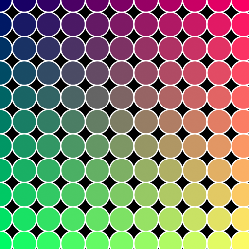
For example, let's create a function for outputting a circle with specific radius and colors at a user-defined position and call that function multiple times using MAXScript FOR loops.
We will also need a function to convert a MAXScript color value to a Hexadecimal color value as used by XML and HTML.
EXAMPLE:
   (
   --The following function converts a MAXScript color value to a Hexadecimal color value
   fn ColorToHex col =
   (
       theComponents = #(bit.intAsHex col.r, bit.intAsHex col.g, bit.intAsHex col.b)
       theValue = "#"
       for i in theComponents do
           theValue += (if i.count == 1 then "0" else "") + i
       theValue
   )

   --The following function outputs a basic circle definition to a given SVG file:
   fn createSVGCircle SVGFile pos radius:100 stroke:yellow fill:red thick:1 =
   (
       format "<circle cx='%' cy='%' r='%' \n" pos.x pos.y radius to:SVGFile
       format "\tstyle='stroke:%; fill:%; stroke-width:%' >\n" (ColorToHex stroke) (ColorToHex fill) thick to:SVGFile
       format "</circle>\n" to:SVGFile
   )

   theSVGFilename = GetDir #userScripts + "\\Circles.svg" --Define an output file name
   theSVGFile = createFile theSVGFilename --Create a text file
   format "<svg xmlns=\"http://www.w3.org/2000/svg\"\n" to:theSVGfile --Output the SVG header lines
   format "\t\txmlns:xlink=\"http://www.w3.org/1999/xlink\">\n" to:theSVGfile

   theStep = 100 --This is the step in pixels along both X and Y
   for y = 0 to 1024 by theStep do --Loop along Y and X with the given Step
       for x = 0 to 1024 by theStep do --and create circles with position and fill color based on the loops:
           createSVGCircle theSVGFile [x,y] radius:(theStep/2) stroke:white fill:(color (x/4) (y/4) 100) thick:5

   format "</svg>\n" to:theSVGfile --End of the SVG body definition
   close theSVGfile --Close the file

   theSVGMap = VectorMap() --Create a new Vector_Map instance
   theSVGMap.vectorFile = theSVGFilename --Assign the output file to the new map
   display (renderMap theSVGMap size:[512,512] filter:true) --Render the map at 512 resolution and display
   )
Here is the resulting map rendered as image:
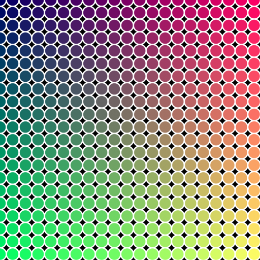
By just changing theStep variable from 100 to 50, we can easily produce more and smaller circles:
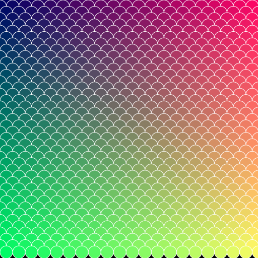
Let's modify the loop further - we can shift every second row by half the step to the side and reduce the Y loop to use half the step.
We will also use a Stroke Thickness of 2 to produce finer outlines:
   --Partial Code Fragment - insert in the above script!
   theStep = 50
   cnt = 0 --introduce a counter variable
   for y = 0 to 1024 by theStep/2 do --divide the vertical step by two
   (
       cnt = 1-cnt --change the counter between 0 and 1 after each row
       for x = 0 to 1024 by theStep do --shift the X by half the step multiplied by the counter (0 or 1):
       (
           createSVGCircle theSVGFile [x+(theStep/2*cnt),y] radius:(theStep/2) stroke:white fill:(color (x/4) (y/4) 100) thick:2
       )
   )
   --End Code Fragment
The result looks like scales!
Including Static Scene Properties
Since MAXScript can easily read properties of scene objects, we could output scene geometry (for example spline shapes) to SVG and thus turn the 3ds Max viewports into a simple SVG Editor!
For example, we can take the Circle drawing function above and implement similar functions for the other typical shapes including Rectangle, Ellipse etc.
Then, we can run through the 3ds Max scene and when we encounter a matching spline primitive, we can grab its properties and output to the SVG file.
EXAMPLE:
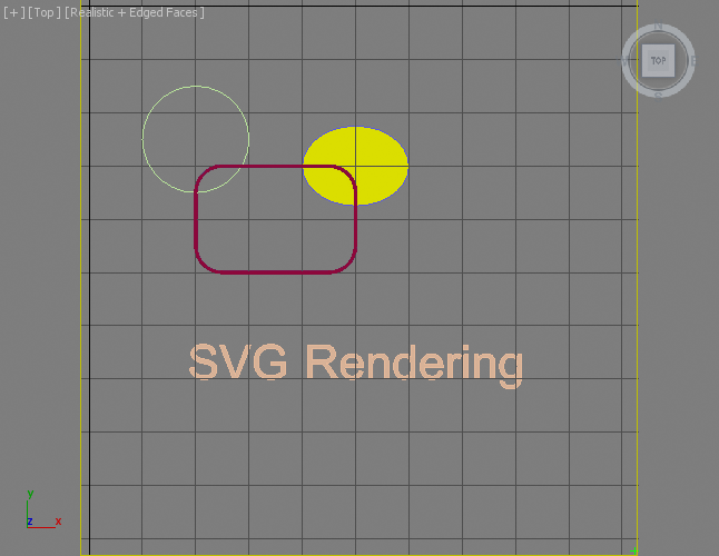
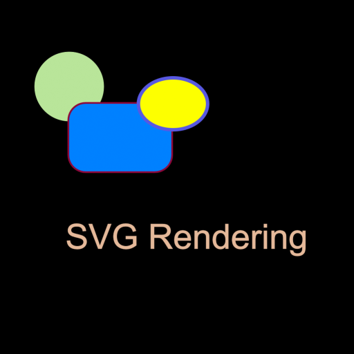
   (
   fn ColorToHex col =
   (
       theComponents = #(bit.intAsHex col.r, bit.intAsHex col.g, bit.intAsHex col.b)
       theValue = "#"
       for i in theComponents do
           theValue += (if i.count == 1 then "0" else "") + i
       theValue
   )

   fn getFillColor obj =
   (
       if classof obj.material == Standard then
           obj.material.diffusecolor
       else
           obj.wirecolor
   )

   fn getPos obj =
   (
       [obj.pos.x, -obj.pos.y]
   )

   fn createSVGCircle SVGFile pos radius:100 stroke:yellow fill:red thick:1 =
   (
       format "<circle cx='%' cy='%' r='%' \n" pos.x pos.y radius to:SVGFile
       format "\tstyle='stroke:%; fill:%; stroke-width:%' >\n" (ColorToHex stroke) (ColorToHex fill) thick to:SVGFile
       format "</circle>\n" to:SVGFile
   )

   fn createSVGEllipse SVGFile pos rx:100 ry:50 stroke:yellow fill:green thick:1 =
   (
       format "<ellipse cx='%' cy='%' rx='%' ry='%'\n" pos.x pos.y rx ry to:SVGFile
       format "\tstyle='stroke:%; fill:%; stroke-width:%' >\n" (ColorToHex stroke) (ColorToHex fill) thick to:SVGFile
       format "</ellipse>\n" to:SVGFile
   )

   fn createSVGRect SVGFile pos w:100 h:100 rx:0 stroke:yellow fill:blue thick:1 =
   (
       format "<rect x='%' y='%' width='%' height='%' rx='%' ry='%'\n" pos.x pos.y w h rx rx to:SVGFile
       format "\tstyle='stroke:%; fill:%; stroke-width:%' >\n" (ColorToHex stroke) (ColorToHex fill) thick to:SVGFile
       format "</rect>\n" to:SVGFile
   )

   fn createSVGText SVGFile pos textString:"SVG" fontSize:100 stroke:green fill:orange thick:1 =
   (
       format "<text x='%' y='%'\n" pos.x pos.y to:SVGFile
       format "\tstyle='font-size:%; font-family:Arial; stroke:%; fill:%; stroke-width:%' >\n" fontSize (ColorToHex stroke) (ColorToHex fill) thick to:SVGFile
       format "%</text>\n" textString to:SVGFile
   )

   theSVGFilename = GetDir #userScripts + "\\MaxShapes.svg"
   theSVGFile = createFile theSVGFilename
   format "<svg xmlns=\"http://www.w3.org/2000/svg\"\n" to:theSVGfile
   format "\t\txmlns:xlink=\"http://www.w3.org/1999/xlink\">\n" to:theSVGfile

   for obj in objects do
   (
       local o = obj.baseobject
       if superclassof o == Shape do
       (
           case classof o of
           (
               Circle: createSVGCircle theSVGFile [obj.pos.x,-obj.pos.y] radius:o.radius stroke:obj.wirecolor fill:(getFillColor obj) thick:o.thickness
               Ellipse: createSVGEllipse theSVGFile [obj.pos.x,-obj.pos.y] rx:(o.width/2) ry:(o.length/2) stroke:obj.wirecolor fill:(getFillColor obj) thick:o.thickness
               Rectangle: createSVGRect theSVGFile [obj.min.x,-obj.max.y] w:o.width h:o.length rx:o.cornerRadius stroke:obj.wirecolor fill:(getFillColor obj) thick:o.thickness
               Text: createSVGText theSVGFile [obj.min.x,-obj.min.y] textString:o.text fontSize:o.size stroke:obj.wirecolor fill:(getFillColor obj) thick:o.thickness
           )
       )
   )
   format "</svg>\n" to:theSVGfile
   close theSVGfile

   theSVGMap = VectorMap()
   theSVGMap.vectorFile = theSVGFilename
   display (renderMap theSVGMap size:[512,512] filter:true)
   )
Here is a screenshot of a scene containing a green Circle, a dark red Rectangle, a purple Ellipse and an orange Text shape.
The Circle has a Radius of 100 and no material or modifiers.
The Rectangle is 300x200 units and has Corner Radius of 50; its Renderable property checked, has a Thickness of 5 and a Standard Material with blue diffuse color assigned.
The Ellipse with size 200x150 has its Thickness set to 10, a MeshSelect modifier on the stack, and has a yellow Standard Material assigned.
The Text has no material and a MeshSelect modifier on the stack.
These objects were placed in the bottom right quadrant of the World Origin, so that their Y coordinates are negative, with the origin in the upper left corner. A green Point Helper shows the position of the 1023,1023 coordinate.
Running the above script produces the following image:
Note that the order of object creation was reflected in the order of shape drawing. The stroke color was taken from the wireframe (object) color; the fill color was taken from the Standard Material's diffuse color, or from the wirecolor property when there was no Material. The Renderable Thickness property was also respected.
Also note that the above script would not take rotations into account and would require significant modifications to support them due to the difference in coordinate systems and object pivot points between 3ds Max and SVG.
Setting the SVG Definition Without External File
The Vector_Map TextureMap provides a dedicated method .SetSvgString() which can be used to pass the SVG XML definition as a string value without pointing at a file on disk.
This means that MAXScript could build a complete SVG description in a String variable or a StringStream and then pass that to the Vector_Map directly.
Using the MXS Token In SVG Files
MAXScript can not only be used to generate SVG files, the 3ds Max Vector_Map TextureMap includes advanced support for MAXScript code embedded in the SVG file itself!
The special mxs token (short for MAXScript) can be used inside the SVG file to include the result of any MAXScript expression in the XML description, as long as it is a String value.
This opens the door for much deeper integration of SVG maps with MAXScript and 3ds Max.
Not only can SVG objects access 3ds Max scene values dynamically, but the Vector_Map will be updated on time changes, allowing for animated maps based on animated scene parameters!
ANIMATED SVG EXAMPLE:
   <svg xmlns="http://www.w3.org/2000/svg"
           xmlns:xlink="http://www.w3.org/1999/xlink">
   <rect x='0.0' y='800.0' width='1024.0' height='100.0'
       style='stroke:#e4d699; fill:#e4d699; stroke-width:1.0' >
   </rect>
   <ellipse cx='mxs(at time currentTime $Ellipse001.pos.x as string)'
       cy='mxs(at time currentTime (-$Ellipse001.pos.y) as string)'
       rx='mxs(at time currentTime ($Ellipse001.width/2) as string)'
       ry='mxs(at time currentTime ($Ellipse001.length/2) as string)'
       style='stroke:#ffffff; fill:#b8e499; stroke-width:3.0' >
   </ellipse>
   </svg>
Saving the above SVG file and loading it with a Vector_Map will produce an animated texture following the Position and Radius animation of an Ellipse001 object in the scene.
Assigning that Vector_Map texture to the Diffuse channel of a Standard Material and assigning it to a Plane produces a dynamic real-time rendering "screen" in the viewport showing the same animation. In addition, the Map display in the Material Editor will also render and show the animation:
Including MAXScript .MS Files In SVG Files
Instead of using inline MAXScript expressions, the mxs() token inside the SVG file can contain function calls to MAXScript functions defined in an external .MS file. This makes the most sense in cases where the calculations are more complex, or the script code has to be modified often and it would be more convenient to separate the MAXScript calculation from the SVG definition.
The SVG file has to call the MAXScript include() function just once with that external .MS file as argument, and any functions defined in it will be accessible to the rest of the SVG body to be called via mxs() . These functions must return String values to be included in the SVG stream.
include() call requires double-quotes for the file name. If the include() call has to be inserted within an SVG property value, the SVG value must be in single quotes to co-exist with the MAXScript call.MAXSCRIPT INCLUDE FILE:
   fn getUserName =
   (
       sysinfo.username --this is already a string
   )
   fn getComputerName =
   (
       sysinfo.computername --this is already a string
   )
   fn getNumCPUs =
   (
       sysinfo.cpucount as string --this is an Integer, so needs conversion to string
   )
Save the above code to "TextIncludeFn.ms" in your UserScripts folder (getDir #userscripts)
SVG FILE:
   <svg  xmlns="http://www.w3.org/2000/svg"
     xmlns:xlink="http://www.w3.org/1999/xlink">
     <text x='100' y='300'
       style='stroke:#00FF88; fill:#005588; font-size:70; font-family:Arial'>
       Hello mxs(include "TextIncludeFn.ms" getUserName())!
     </text>
     <text x='100' y='400'
       style='stroke:#00FF88; fill:#005588; font-size:70; font-family:Arial'>
       Your Computer mxs(getComputerName())
     </text>
     <text x='100' y='500'
       style='stroke:#00FF88; fill:#005588; font-size:70; font-family:Arial'>
       has mxs(getNumCPUs()) CPUs
     </text>
   </svg>
Save the above SVG definition as "TextIncludeFn.svg" in the same folder as the .MS file - (getDir #userscripts)
Note that the include() call is performed just once before the first use of getUserName(), all further mxs function calls don't need the .MS file re-included!
CREATE VECTORMAP TEXTUREMAP:
   theVMap = VectorMap() --create a vector map
   theSVGFileName = GetDir #userScripts + "\\TextIncludeFn.svg" --define the file name of the SVG map source
   theVMap.vectorfile = theSVGFileName --assign the SVG file to the map
   theTextImage = bitmap 512 512 --create an image for the text
   renderMap theVMap into:theTextImage filter:true --render the Vector Map into the image
   display theTextImage --display the resulting image
RESULT EXAMPLE:

Using SVG To Render Text To Bitmap
In the following example, we will use the text rendering capabilities of the Vector_Map TextureMap to generate a bitmap containing render time information.
We will create a bitmap using the renderMap() function and overlay it on top of an image produced using the render() function.
EXAMPLE:
   renderW = 640 --define the render output width
   renderH = 480 --define the render output height
   textSize = 20 --define the overlay text's height in pixels
   theImage = bitmap renderW renderH --define a bitmap for the render output
   st = timestamp() --get a timestamp before rendering
   render to:theImage vfb:off --render the scene into the existing bitmap
   et = timestamp() --get a time stamp after rendering
   theTime = "Image Render Time: " +((et-st)/1000.0) as string + " seconds." --define the text to overlay
   theVMap = VectorMap() --create a vector map
   theSVGFileName = GetDir #userScripts + "\\RenderInfoMap.svg" --define the file name of the SVG map source
   theSVGFileHandle = createFile theSVGFileName --create a new text file with that name
   format "<svg xmlns=\"http://www.w3.org/2000/svg\"\n" to:theSVGFileHandle --define the svg header
   format "\txmlns:xlink=\"http://www.w3.org/1999/xlink\">\n" to:theSVGFileHandle
   format "\t<text x='0' y='%'\n" textSize to:theSVGFileHandle --define the text position
   format "\t\tstyle='font-size : %;\n" textSize to:theSVGFileHandle --define the text font size
   format "\t\tfont-family: Arial; \n" to:theSVGFileHandle --define the text font family
   --format "\t\tstroke: #ffffff;\n" to:theSVGFileHandle --define the text outline. Bad Idea, makes it too thick
   format "\t\tfill: #ffffff\n" to:theSVGFileHandle --define the fill color of the text as white
   format "\t\t'\n" to:theSVGFileHandle --close the font style definition
   format "\t>%</text>\n" theTime to:theSVGFileHandle --output the text to display
   format "</svg>\n" to:theSVGFileHandle --end the SVG definition
   close theSVGFileHandle --close the SVG file
   theVMap.vectorfile = theSVGFileName --assign the SVG file to the map
   theVMap.alphasource = 0 --enable Alpha output
   theTextImage = bitmap 1000 1000 --create an image for the text
   renderMap theVMap into:theTextImage filter:true --render the Vector Map into the image
   --composite the text from the image onto the rendered image
   pasteBitmap theTextImage theImage (box2 0 0 1000 (textSize*2.0)) [5,renderH-(textSize*1.5)] type:#composite
   display theImage --display the result
RESULT EXAMPLE:

Learn More About SVG and Vector_Map
A three-part tutorial in the How To... section demonstrates the use of the Vector_Map and the SVG format to render geometry objects as polygons:
- How To ... Develop An SVG Polygon Renderer - Part 1 - Basic Flat Rendering
- How To ... Develop An SVG Polygon Renderer - Part 2 - Back-To-Front Sorted Rendering
- How To ... Develop An SVG Polygon Renderer - Part 3 - Facets with Blinn Lighting and Shading