How To ... Develop An SVG Polygon Renderer - Part 1
The following is part one of a three parts tutorials series demonstrating the use of MAXScript together with the Vector_Map TextureMap. MAXScript will be used to write an SVG XML file to disk containing polygon entities representing the faces of scene objects to be rendered. The SVG file can be loaded in any Web Browser or rendered to a bitmap via the renderMap() function. For more information about the use of MAXScript to create SVG files, please see the Vector_Map TextureMap and MAXScript topic.
In this first part of the tutorial, we will simply output all camera-facing triangle faces of all geometry object.
In the second part of the tutorial, we will sort the polygons by depth to make sure the faces do not overlap incorrectly.
In the third part of the tutorial, we will add support for material colors and implement lighting.
Related topics:
Vector_Map TextureMap and MAXScript
NATURAL LANGUAGE
Define a function to convert MAXScript Colors to Hexadecimal values (Web Format)
Create a new SVG text file and output its header.
Collect information about the view transforms and size.
Loop through all visible geometry scene objects
Get the World Space TriMesh and loop through its faces
Calculate the position of the three vertices of each face in image space and output them to SVG
Close the SVG, create a new Vector_Map instance and render it into a bitmap to display.
SCRIPT:
   (
   fn ColorToHex col =
   (
       local theComponents = #(bit.intAsHex col.r, bit.intAsHex col.g, bit.intAsHex col.b)
       local theValue = "#"
       for i in theComponents do
           theValue += (if i.count == 1 then "0" else "") + i
       theValue
   )

   local st = timestamp()
   local theFileName = (getDir #userscripts + "\\PolygonRendering3.svg")
   local theSVGfile = createFile theFileName
   format "<svg xmlns=\"http://www.w3.org/2000/svg\"\n" to:theSVGfile
   format "\t\txmlns:xlink=\"http://www.w3.org/1999/xlink\">\n" to:theSVGfile

   local theViewTM =  viewport.getTM()
   theViewTM.row4 = [0,0,0]

   local theViewTM2 = viewport.getTM()
   local theViewSize = getViewSize()
   local theViewScale = getViewSize()
   theViewScale.x /= 1024.0
   theViewScale.y /= 1024.0

   local theStrokeThickness = 3

   gw.setTransform (matrix3 1)
   for o in Geometry where not o.isHiddenInVpt and classof o != TargetObject do
   (
       local theStrokeColor = white
       local theFillColor = o.wirecolor

       local theMesh = snapshotAsMesh o
       for f = 1 to theMesh.numfaces do
       (
           local theNormal = normalize (getFaceNormal theMesh f)
           if (theNormal*theViewTM).z > 0 do
           (
               local theFace = getFace theMesh f
               local v1 = gw.transPoint (getVert theMesh theFace.x)
               local v2 = gw.transPoint (getVert theMesh theFace.y)
               local v3 = gw.transPoint (getVert theMesh theFace.z)

               v1.x /= theViewScale.x
               v1.y /= theViewScale.y
               v2.x /= theViewScale.x
               v2.y /= theViewScale.y
               v3.x /= theViewScale.x
               v3.y /= theViewScale.y

               format "\t<polygon points='%,%  %,%  %,%' \n" v1.x v1.y v2.x v2.y v3.x v3.y to:theSVGfile
               format "\tstyle='stroke:%; fill:%; stroke-width:%'/>\n" (ColorToHex theStrokeColor) (ColorToHex theFillColor) theStrokeThickness to:theSVGfile
           )--end if normal positive
       )--end f loop
   )--end o loop

   format "</svg>\n" to:theSVGfile
   close theSVGfile
   local theSVGMap = VectorMap vectorFile:theFileName alphasource:0
   local theBitmap = bitmap theViewSize.x theViewSize.y
   renderMap theSVGMap into:theBitmap filter:true
   display theBitmap
   format "Render Time: % sec.\n" ((timestamp()-st)/1000.0)
   )
Step-By-Step
(We open a bracket to ensure all following code will be evaluated in its own local scope.
fn ColorToHex col =
(
    local theComponents = #(bit.intAsHex col.r, bit.intAsHex col.g, bit.intAsHex col.b)
    local theValue = "#"
    for i in theComponents do
        theValue += (if i.count == 1 then "0" else "") + i
    theValue
)
This function takes a MAXScript Color Value as argument.
It then creates an array where the Red, Green and Blue components of the Color Value are converted individually to Hexadecimal values (these are returned as Strings by the bit.intAsHex() method).
A String variable called theValue is initialized to "#" which is the prefix of Hexadecimal Colors used in Web HTML and XML files.
A For Loop then iterates through the already converted components in the array and accumulates into the String variable. Where the String has a single character, a leading zero is included.
The Loop produces the whole Hexadecimal value, for example Red turns into "#ff0000".
The variable theValue is returned as the result of the function.
local st = timestamp()This variable takes the current system time in milliseconds.
We will use it to calculate how long it took to output the SVG and render the resulting Vector_Map to an image in the end of the script.
local theFileName = (getDir #userscripts + "\\PolygonRendering1.svg")
local theSVGfile = createFile theFileName
We define a file name for our SVG file - it will be stored in the UserScripts folder.
Then we use this file name to create a new ASCII Text file - we will output the SVG XML definition to it.
format "<svg xmlns=\"http://www.w3.org/2000/svg\"\n" to:theSVGfile
format "\t\txmlns:xlink=\"http://www.w3.org/1999/xlink\">\n" to:theSVGfile
Every SVG file must start with a header describing the content of the XML.
We format this standard information to the newly created text file.
local theViewTM =  viewport.getTM()
theViewTM.row4 = [0,0,0]
We will need the view transformation matrix of the current viewport, but without the translation part to transform Face Normals into view space to check for their orientation (facing the viewer, or facing away from the viewer).
This is why we zero out the .row4 which contains the translation part.
local theViewTM2 = viewport.getTM()We will also need the full view transformation matrix for the vertex coordinate transformations.
local theViewSize = getViewSize()
local theViewScale = getViewSize()
theViewScale.x /= 1024.0
theViewScale.y /= 1024.0
In order to convert the 1024x1024 canvas space of the Vertex_Texture, we will need to get the Viewport Size and the Viewport Scale.
The View Size will contain the actual pixel resolution we want to render.
The View Scale will contain the scaling factor to convert from the Vertex_Texture to the render output size.
local theStrokeThickness = 3Since we will have a solid fill color without any shading, it is important to make the edges visible, so we set a variable to define the Stroke Thickness as 3.
gw.setTransform (matrix3 1) We will be using a graphics window (gw) function to transform the vertices from world space to view space, so we have to ensure the gw transformation matrix is set to the identity matrix.
for o in Geometry where not o.isHiddenInVpt and classof o != TargetObject do
(
This For Loop will visit all GeometryClass objects and filter out only those that are not hidden for some reason and are not of the TargetObject class which has no valid mesh.
    local theStrokeColor = white
    local theFillColor = o.wirecolor
The rendering will use two colors - white for the outlines (Stroke Color), and the object color (a.k.a. wireframe color) for the Fill Color.
local theMesh = snapshotAsMesh oWe grab the world state of the current object's mesh into a variable.
This will allow us to loop through its Faces and access Vertex and Normal data.
    for f = 1 to theMesh.numfaces do
    (
This For Loop will go through all faces of the current mesh.
local theNormal = normalize (getFaceNormal theMesh f)First of all, we will need the face normal.
Although it should be normalized already, it does not hurt to apply normalize() to it to be completely sure.
        if (theNormal*theViewTM).z > 0 do
        (
We want to make sure we only draw faces whose normals are pointing at the camera (also known as Backface Culling).
To do this, we multiply the Normal which was originally in World Space by the View Transformation Matrix (the one with Translation part set to zero). This converts the Normal into View space.
At this point, since the view is looking at the scene along its -Z axis, any Z values that are negative are parallel to the viewing direction (facing away from the viewer), while positive Z values mean "facing the viewer".
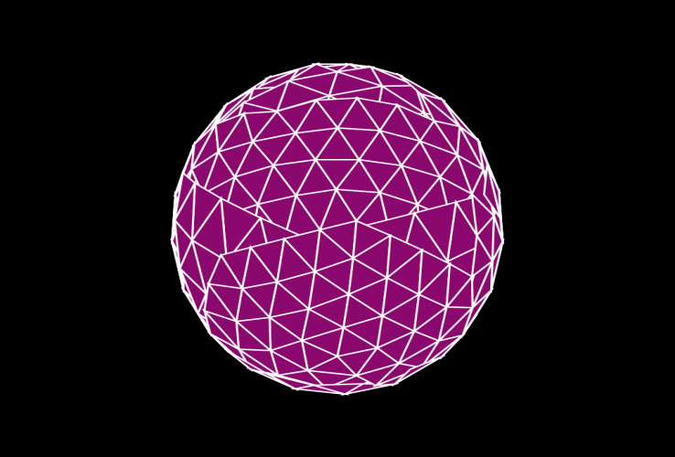
There are still some problems at the edges of the Geosphere because there is no sorting by depth (we will add this in Part 2).

Inverting the test to if (theNormal*theViewTM).z < 0 do will cull the front faces and only draw the backfaces:

Without this test, ALL faces of the mesh would be drawn, and since we are not performing any other sorting yet, the result would be very messy:
local theFace = getFace theMesh fWe will need the face definition to access its vertices.
            local v1 = gw.transPoint (getVert theMesh theFace.x)
            local v2 = gw.transPoint (getVert theMesh theFace.y)
            local v3 = gw.transPoint (getVert theMesh theFace.z)
Now we can get each of the face's 3 vertices and transform them into the current view space.
            v1.x /= theViewScale.x
            v1.y /= theViewScale.y
            v2.x /= theViewScale.x
            v2.y /= theViewScale.y
            v3.x /= theViewScale.x
            v3.y /= theViewScale.y
But since we have to provide the screen coordinates in the range from 0 to 1023 for the SVG to remap its own canvas to the current view, we have to divide the X and Y components of the transformed vertices by the View Scale factor we calculated in the beginning of the script. This way, a pixel with X at the right border of the viewport will map to 1023, and one at the center of the viewport will be placed exactly at the center of the SVG canvas, regardless of its viewport pixel coordinates.
            format "\t<polygon points='%,%  %,%  %,%' \n" v1.x v1.y v2.x v2.y v3.x v3.y to:theSVGfile
            format "\tstyle='stroke:%; fill:%; stroke-width:%'/>\n" (ColorToHex theStrokeColor) (ColorToHex theFillColor) theStrokeThickness to:theSVGfile
Now we can output an SVG polygon definition by providing the X and Y coordinates of the three transformed vertices.
We also define the style of the polygon to use the stroke color we defined, the fill color set to the object's color, and the thickness of the stroke currently set to 3.
        )--end if normal positive
    )--end f loop
)--end o loop
We can close the IF test's body and the two nested loops - the one looping through all faces of the current object, and the other looping through all geometry objects.
format "</svg>\n" to:theSVGfile
close theSVGfile
We can also end the SVG XML body with a closing tag and also close the text file.
local theSVGMap = VectorMap vectorFile:theFileName alphasource:0
local theBitmap = bitmap theViewSize.x theViewSize.y
renderMap theSVGMap into:theBitmap filter:true
display theBitmap
Now we can build a new VectorMap using the text file name we output to, and with Alpha channel enabled.
We will output to a predefined bitmap with size based on the exact pixel size of the current viewport.
Then we can render the VectorMap into that bitmap with filtering enabled and finally display the resulting bitmap value.
format "Render Time: % sec.\n" ((timestamp()-st)/1000.0)Before ending the script, we can print the time it took to save the SVG and render the map.
Since the timestamp() is in milliseconds, we have to divide by 1000.0 to produce a value in seconds.
)Finally, we close the local scope of the script.
Using The Script To Render Geometry
Let's try to render some geometry primitives through a Perspective viewport.

As you can see, the Teapot which consists of 4 elements - Body, Lid, Handle and Spout - has severe sorting problems - the Spout is partially drawn over the Body.
A similar problem occurs when rendering multiple individual objects depending on the position of the camera and the order of creation.
In the following example, the Cylinder was created second after the Teapot, while the Sphere which is in fact located behind the Teapot, was created third:

In the second part of the tutorial, we will sort the polygons to avoid incorrect overlapping within a single object and between multiple objects to fix the problems illustrated above.