Several updates have been made to Character animation workflows, from a tool for changing rotation order, support for multiple skin clusters, and a new way to view skin weights numerically.
Numeric weight visualization

Support for multiple Skin Clusters
You can now have more than one Skin Cluster on a single piece of geometry, opening up new possibilities for animators and riggers.
Use multiple Skin Clusters to layer deformations, for example, creating a layer for squash and stretch, a layer for kinematic motions, and another for fine details. Also, using Multiple skin clusters opens up possibilities for alternate weighting for a variety of needs, both technical and artistic, even exploratory or derived from different techniques such as traditional painting, and volumetric weighting, and so on.
You can find the settings for working with multiple skin clusters in the options windows of most tools in the Skin menu. See Manage multiple Skin Clusters.
To try the feature for yourself, you can also download and open the Interactive Tutorial from the AREA.
Change Rotation Order setting
Changing the Rotation order of a gimbal locked shoulder using Reorder Rotation
A new set of options, Reorder Rotation... have been added to the Modify menu to let you change the rotation axes of a selected object as well as evaluate and shows the likelihood of gimbal lock for each.
Use the Reorder Rotation Options when you want to change the rotation order of a control after its been animated, or when you don't want to change the object pose.
New Joint draw style
A walkthrough of different Joint Draw Styles
When you select Joint from the Draw Style menu only a sphere displays. (If you choose Bone, a sphere and a cone is shown.)
This Joint draw style is useful for working with rigs with multiple child joints in a small area, where it can be difficult to view joint influences.
New Rigging Math Nodes
| New Nodes | |||
|---|---|---|---|
|
absolute |
cos |
log |
pi |
|
acos |
determinant |
max |
power |
|
and |
equal |
min |
round |
|
asin |
floor |
modulo |
rotateVector |
|
atan |
greaterThan |
multiply |
sin |
|
atan2 |
inverseLerp |
negate |
smoothStep |
|
average |
length |
normalize |
sum |
|
ceil |
lerp |
not |
truncate |
|
clampRange | lessThan |
or |
tan |
New HumanIK Character template
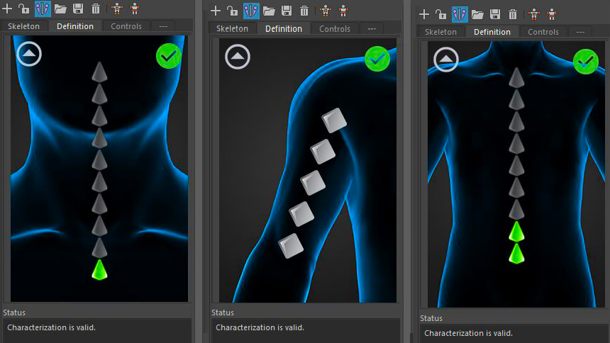
A new HumanIK character template, FullRigControlsConfig.xml, has been added to the two existing rig templates (CharacterControlsConfig.xml and CustomRigControlsConfig.xml). This new template provides a comprehensive list of all spine, neck, hand and foot joints, extra shoulder joints, as well as additional finger and toe bones.
To load the new FullRigControlsConfig.xml template:
Select
 >
Edit > Custom Rig > Load UI Configuration.
>
Edit > Custom Rig > Load UI Configuration.
- Windows: C:\Program Files\Autodesk\<Maya version>\resources\CharacterControls
- Mac OS X: /Applications/Autodesk/<Maya version>/Maya.app/Contents/resources/CharacterControls
- Linux:/usr/autodesk/Maya/resources/CharacterControls
By default, the character controls templates are created in CharacterControls directory during installation. These files are used to create the default layouts for the Controls and Custom Rig tabs.
Global Scaling Setting for Proximity Wrap deformers
Before and After: a complex deformation with and without the Use Transform As Deformation and Driver Cluster Matrix attributes applied
There are new ways to control to how the Proximity Wrap driver is used to influence the deformation of the inputGeometry of the proximityWrap. The driver verts can be moved by deformation and/or transformation of the driver.
This new functionality deals with the methods by which the location of the verts of the driver are used for deforming the inputGeometry.
- A new Use Transform As Deformation option specifies whether the transform of the driver is used as a deformation of the driver verts or whether it is kept separate. With the option turned off, the scaling and rotation of the driver are better preserved when used to deform the input geometry of the proximityWrap.
- If the deformation of the driver has an implicit transformation, you can make this transformation explicit by going to the Node Editor, and connecting a matrix to the Proximity Wrap's Driver Cluster Matrix attribute. This connection uses the transformation information to better preserve the rotation and scaling.
See Global Scaling Setting for Proximity Wrap deformers for a demonstration of these changes.
You can find Use Transform As Deformation option in the Proximity Wrap options and the Proximity Wrap Drivers window.
Additional matrix node controls
A new matrix setting has been added to both the aimMatrix and blendMatrix nodes. SpaceMatrix is a set of Pre and Post Matrix floats that multiply inputs and outputs, letting you create setups without the need for extra multMatrix nodes.
New Space Modes for UVpin, Proximity pin, and skinCluster Nodes
A new Relative Space mode menu has also been added to the UVpin and Proximitypin deformer and Attribute Editor skinCluster node options:
Use the Relative Space mode menu to choose the space your nodes are evaluated from:
-
Local
-
World
-
Custom
World is the default setting, Local uses the geometry space for evaluation, so that no double deformations/transformations occur if the geometry moves, and Custom lets you add an external matrix as the space. These options let you avoid issues where double deformations or transformations when the geometry parent is moved.
If your geometry has no local values for transformation, objects are parented to the parent of the geometry instead of the geometry.
See UVpin options, Proximity pin options and skinCluster options.