Find an injection location
Run a Gate Location analysis to find suitable injection locations and automatically place an injection location on a copy of the model.
The location of the injection point on the model affects whether the part will suffer from defects such as short shots, weld lines or over packing.
If the Analysis Wizard is not displayed, click
 (Home tab > Molding Process Setup panel > Analysis Wizard).
Select the Sequence tab and select the Gate Location checkbox.
Click Next to display the Gate Location tab.
Ensure the Advanced Gate Locator algorithm is selected, and enter 1 in the Number of gates text box.
Click Next to display the Material tab.
Select Generic PP: Generic Default in either the Specific material area or the Commonly used materials list.
This is the default thermoplastics polypropylene material.
Select Finish to close the Analysis Wizard.
You can select regions of the model where you do not want to allow injection locations.
The default selection method is using a tolerance angle. Adjacent areas are selected when they meet at an angle less than the tolerance angle. By increasing the tolerance angle, or selecting a number of regions, you can prohibit injection locations from being placed on the front face of the cellphone cover.
Click
 (Boundary Conditions tab > Injection Locations panel > Prohibited Gate Regions).
The Tools tab displays the Prohibited Gate Regions pane.
The Selection Method pane allows you to define how a region will be chosen. Ensure Tolerance Angle is selected form the drop down box. Scroll down, if necessary, to see this section of the dialog.
Enter a Tolerance of 35 degrees.
Click the front face of the model to prohibit injection locations from being placed on this surface.
You may need to select multiple regions to prohibit the entire front face of the cell phone as there are several fillets.
Prohibited regions are displayed in red.

Click Close.
Prohibited gate regions will be ignored when you run the Gate Location analysis.
Click
 Analyze to run the Gate Location analysis.
The Gate Location analysis, using the Advanced Gate Locator algorithm produces two results when analyzing the best position for one gate.
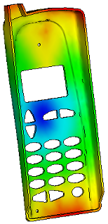
- Flow resistance indicator result
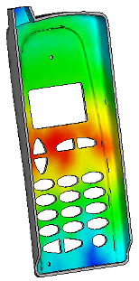
- Gating suitability result
- This result rates each place on the model for its suitability for an injection location. Areas with the same color represent equally suitable positions. If the injection location is not suitable due to design constraints, consider the other red regions in the Gating suitability result when placing a different injection location.
Rotate the model so you can see the back of the cellphone cover.
Select the Flow resistance indicator result in the Study Tasks pane.
The lowest flow resistance, indicated in blue, is in the center of the model.
Select the Gating suitability result in the Study Tasks pane.
The most suitable injection locations are indicated in red.
You can add an injection location at the best position indicated by the analysis, using the Gate Location Summary.
Click Summary in the Study Tasks pane, then click the Gate Location tab.
Click Apply All to place an injection location using the Shape and the Coordinate specified in the New Gate Locations table.
Click Create Copy.
A new study is created, containing one injection location. The study name is currently highlighted.
Right-click on the study name, and rename the study cellphone_study_1, then press Enter.
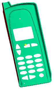
The new study has an injection location at the center of the back of the cellphone cover. You can now run a Fill analysis.
Parent topic: Fill+Pack analysis (tutorial)
Previous topic: Manipulate the model
Next topic: Run a Fill+Pack analysis