Compression surfaces
In compression type molding process simulations, the surface of your model must be assigned the "compression surface" property type so the software can identify where compression will occur.
Midplane models
For Midplane analyses, the elements of the model are selected and assigned the property type "compression surface". The nodes associated with these elements are then considered to move with the press plate.
3D models
For 3D analyses, you select the model surface and assign it the property type "Compression element (3D)". Unless you manually intervene, the software will then automatically assign the fixed and moving side based on your analysis setup.
Automatic assignment of element properties
In most cases the automatic assignment will provide an accurate simulation of the molding process. The compression direction can be set either in the +Z or the -Z direction; the default direction is -Z.
Automatic assignment of model surfaces
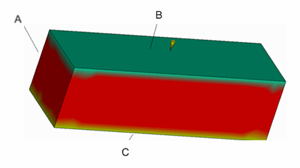
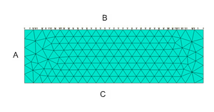
Compression surface property result
where A = side surface, B = compression surface, and C = fixed surface
Manual assignment of surface properties
In some cases, particularly with complex geometries, poor mesh quality, or special, proprietary processes, the assignment will need to be refined. In these cases the three compression surface types, shown in the figures above, can be assigned manually.
There are four (4) compression surface property options:
Automatic
The determination is performed by the code. This is the default setting.
Compression (moving) surface
The compression (moving) surface is considered to be the press side of the cavity and will follow the press movement exactly.
Fixed surface
The fixed surface is considered to be the fixed side of the cavity. No movement occurs during compression.
Side surface
The side surface is illustrated by A in the figure above. There is no movement of nodes with this compression surface property in the direction normal to the compression direction, but there can be movement in the compression direction.