Fixing high aspect ratios
In this task, you will use the two mesh fixing tools, Merge Nodes and Swap Edge, to eliminate high aspect ratio elements.
 Download the files for this tutorial fromAutodesk Knowledge Network - Mesh editing tutorial.
Aspect ratio: Swap Edge.
Ensure the Tutorial 3 project you created in Task 1 is open.
Click
 ( (Home tab > Import panel > Import)).
Navigate to where you saved your tutorial files
In the Files of type drop-down list, select Study files(*.sdy).
Click on the file tutorial_3_task_4.sdy and click Open.
The connectivity issues from the previous task have been corrected on this model. We are going to isolate elements with a defined range of aspect ratios and place them onto a diagnostic layer.
Click
 (Mesh tab > Mesh Diagnostics panel > Aspect Ratio) to display the Aspect Ratio Diagnostic pane.
Enter a Minimum aspect ratio value of 8, and a Maximum aspect ratio value of 15.
Select Place results in diagnostics layer to move elements with aspect ratios within the above range to their own layer.
Click Show, and then click Close.
In the Layers panel, right-click the layer with the name Diagnostic results and select Hide All Other Layers.
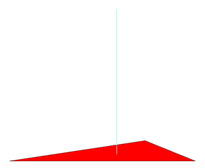
The high aspect ratio elements are highlighted with projecting spikes. You may need to rotate the model slightly to see the spikes.
Click Mesh tab > Entity Navigator and select T311 from the drop-down box.
A High Aspect ration triangle is displayed. To understand how to deal with a high aspect ratio element, you need to see the adjacent elements.
Click
 (Layers pane > Expand Layer ).
The Expand Layer dialog appears. Set Expand current selection by to 1 level(s).
Click OK.
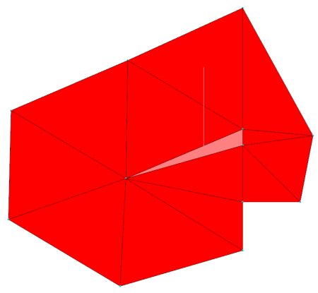
The display should now be similar to the following:

Click
 (Mesh tab > Mesh Edit panel > Swap Edges).
Select the element with the high aspect ratio, which has the spike protruding from it.
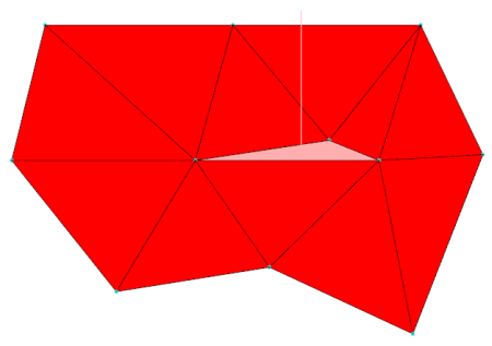 The element number T311 will appear in the Select first triangle box of the Swap Edge tool pane.
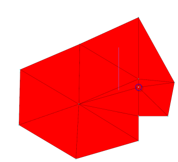
Click the element attached to the long edge of the high aspect ratio element:
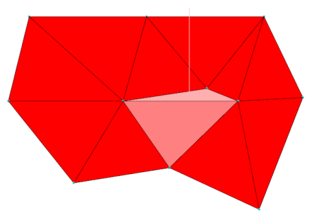 The second element's number T7672 will appear in the Select second triangle box of the Swap Edge tool pane.
Click Apply.
The high aspect ratio element has been eliminated by altering the nodes that are joined to form the local surface.
Click Close on the Tools pane.
Click Mesh tab > Entity Navigator and select T497 from the drop-down box.
Previously we swapped edges to resolve the high aspect ratio element. In this instance, we would replace a high aspect ratio element that runs across the screen with one that runs up the screen. We need a different approach, which is to merge nodes.
Click
 (Mesh tab > Mesh Edit panel > Merge Nodes).
The Merge Nodes pane appears.
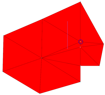
Click on one of the nodes along the short edge of the high aspect ratio element. This first node is the target of the merge.
Click on the other node along the short edge of the high aspect element. This is the node that will be merged onto the target node.
The sequence of node selection will alter the resultant merge. Autodesk Moldflow Insight has filled in the node identification numbers in the Input Parameter boxes of the Merge Nodes pane.
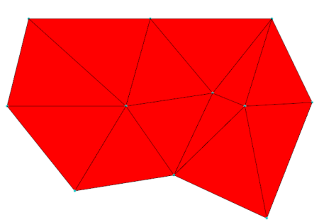
Click Apply.
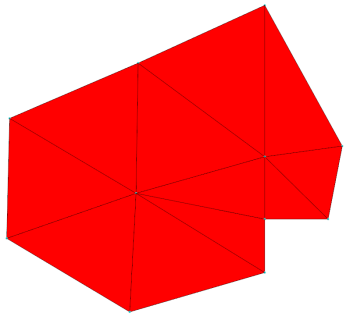
The second node is merged into the first node, and the surrounding elements are adjusted accordingly.
Close the Merge Nodes dialog.
The above methods can be used to eliminate, one by one, the remaining high aspect ratio elements in the mesh.
In the next task, you will learn how to fix free edges.
Parent topic: Edit the mesh
Previous topic: Fix bad connectivity
Next topic: Fixing invalid free edges