Midplane mesh
Historically, a part was meshed by creating a plane through the middle of the part and then assigning the thickness to the surface.
 Download the files for this tutorial from Autodesk Knowledge Network - Meshing tutorial.
This surface was then meshed with triangular elements that are joined along their edges and corners (called nodes). The thickness of the part is stored for each element. The analysis uses the shape of the plane and the thickness of each element as a structure to simulate the polymer flow.
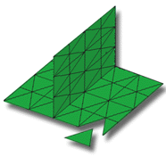
Midplane mesh is still used for large flat parts such as car bumper bars. For large models, the lower element count, compared to the other meshing technologies, make this a viable alternative for at least preliminary investigations.
Some results are also only available after using Midplane analysis.
In this task, you will:
- Import a Midplane model
- Investigate how the mesh is structured
- Click
 (Start & Learn tab > Launch panel > New Project).
 - Enter Mesh tutorial for the Project Name.
- Click OK.
- Click
 (Home tab > Import panel > Import).
 - Select the Files of type drop-down list. The list of file types directly supported is shown. Select Study files (*.sdy).
- Navigate to the where you saved the tutorial files.
- Select dustpan_midplane.sdy then click Open.
- Rotate and zoom in on the model to investigate the part geometry and the way the model has been represented as a Midplane model.
- Note that the Midplane Mesh type and number of elements in the model are displayed in the Study Tasks pane.
Click the Next topic link below to move on to the next task of the tutorial.
Parent topic: Mesh
Next topic: Dual Domain mesh