Manual cavity duplication
Duplicate the cavity, gate, and runner from the previous task to create a two-cavity layout.
Click
 (Geometry tab > Selection panel > Select All).
Click
 (Geometry tab > Utilities panel > Move) and select
  Reflect from the Move drop-down list.Note: Using the Reflect tool, you will obtain a mirror image of the part. The Rotate tool will give you a copy of that part.
Select YZ plane from the Mirror drop-down list.
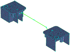
Activate the Reference point box and then click the node furthest from the part.
The coordinates of the node you created earlier should now appear in the Reference point box.
Select Copy.
Check Attempt connection to existing model .
When this option is on, automatic adjustments will be made to the model where necessary, for example, merging coincident or very close nodes to ensure that the copied entities are correctly connected to the original entities.
Click Apply and then Close.
Rotate the model to -140 140 -35. Enter the values in the Rotation Angle text box
 (View tab > Viewpoint panel > Rotation Angle) and press Enter on your keyboard.
Click
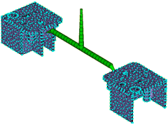
 (View tab > Navigate panel > Zoom All) to rescale the model.
There should now be two connected cavities, as shown in the following image:
Now you will create the sprue. This time we will demonstrate that you can create the required curve directly without first creating nodes. Click
 (Geometry tab > Create panel > Curves) and select
  Create Line from the Curves drop-down list .
Activate the First Coordinate box and click the node in the center of the runner.
In the Second Coordinate area of the dialog, select Relative and enter the coordinates 0 0 50.
Click
 Browse next to the Create As text box.
Click the New button and select Cold sprue .
From the Shape is drop-down box, select Tapered (by angle) , and click Edit dimensions....
Enter 6 (mm) in the Start diameter box, and -2 (degrees) in the Tapered angle box.
Click OK three times to return to the Create Curves dialog and then click Apply.
Click Close.
Now that you have created the geometry for the runner system, mesh the new curves. Click
 (Mesh tab > Mesh panel > Generate Mesh).
Ensure that Remesh already meshed parts of the model is not selected.
This ensures that only the new curves are meshed.
Accept the defaults for the other options on the dialog and click Mesh, to launch the Simulation Compute Manager.
In the Simulation Compute Manager, select the solve location, then click Launch.
- Note: If the Mesh Generation Tip dialog appears, click Close to continue the meshing operation.
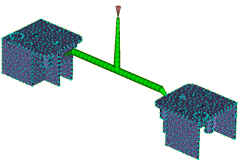
The new curves are meshed and a Mesh Complete message dialog appears. Click OK to close the message dialog.
The model should now appear as shown in the following image:
Investigate the runner system you have created. Rotate the model to -90 0 0. Enter the values in the Rotation Angle text box
(View tab > Viewpoint panel > Rotation Angle) and press Enter on your keyboard. Zoom in on the gate region.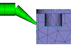
The gate is made up of several beam elements. For accurate modeling, a beam must be made of at least three elements. You can remesh this area to change the mesh refinement.
Click
 (Mesh tab > Mesh Edit panel > Advanced > Remesh Area).
Select the beam elements in the gate. Each of these elements has a unique element number that is displayed in the Select entities to remesh text box.
The Edge length box shows the current edge length in mm. If this length is reduced, there will be more beam elements in the gate.
Enter a different number into the Edge length box and click Preview. Alternatively, change the Scale slider and see the effect instantly.
Click Close to exit the dialog without incorporating the changes.
Check mesh connectivity. Click
 (Mesh tab > Mesh Diagnostics panel > Connectivity).
To check the connectivity of the runners with the cavities, click the element at the top of the sprue. Then click Show in the Mesh Connectivity Diagnostic dialog.
You can see that all the mesh elements are connected.
Click Close on the Mesh Connectivity Diagnostic dialog in the Study pane.
Right-click in the Model panel and select
 (View > Mesh Diagnostics) to remove the display.
Set the injection location and analyze.
Click
 (Home tab > Molding Process Setup > Injection Locations).
Click the top of the sprue.
Right-click the injection cone and select Finish Set Injection Locations.
Note that there are
 Check marks beside all the pre-analysis steps and that the
  Analyze icon and text is active.
The model is now ready for analysis.
This task has shown how to create a runner system manually.
The runners were created by creating nodes, creating curves connecting those nodes, assigning runner, gate, and sprue properties to the curves, and then meshing the runner system.
Parent topic: Set up a multi-cavity Fill analysis (tutorial)
Previous topic: Manual runner system creation
Next topic: Design a multi-cavity layout