Manual runner system creation
In this task you complete the steps required to construct curves that the runner system is built along.
In this task, you;
- Manually create a runner system
 Download the files for this tutorial from Autodesk Knowledge Network - Setting up a Multi Cavity Fill analysis tutorial.
To build the runner system, you will specify nodes outside the model that the runner system will connect to.
Open the Modeling Tutorial project.
Click
 (Home tab > Import panel > Import).
Select the Files of type drop-down list. The list of file types directly supported is shown. Select Study files (*.sdy) .
Navigate to where you saved the tutorial files.
Click the file model_4.sdy and click Open.
Click
 (View tab > Viewpoint panel > Rotation Angle) Rotate the model t. Enter the valuesand
Enter 0 85 90 in the Rotation Angle press Enter on your keyboard to rotate the model to the required orientation.
In the Layers pane, ensure that the New Nodes layer is selected.
You will now create nodes to define the gate and runner system.
Click
 (Geometry tab > Create panel > Nodes) and select
  Node by Offset from the Nodes drop-down menu.
The Node By Offset tool pane appears. You are asked to enter the coordinates of a Reference node in the Base text box. The node you select will become the injection location.
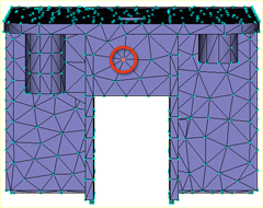
Select the node indicated below as the Reference node.
The coordinates of the selected node appear in the Base text box.
Click in the Offset text box to activate it.
Enter -10 0 7, and click Apply. A new node is generated 10 mm in front of the model and 7 mm higher than the Reference node you selected.
Click
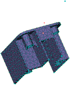
(View tab > Viewpoint panel > Rotation Angle) .Enter -90 165 0 in the Rotation Angle text box and press Enter on your keyboard.
The node you just created is visible to the right of the model and level to the top of the part.
Click
 (View tab > Navigate panel > Zoom All) to rescale the model and view the new node you created more clearly.
Click
 (View tab > Navigate panel > Select).
Click in the Base text box in the Tools pane and click the newly created node.
You will now create a second node offset from the first node by 50mm.
Enter -50 0 0 in the Offset text box and click Apply, then click Close.
Click
(View tab > Viewpoint panel > Rotation Angle) Enter -65 125 45in the Rotation Angle text box and press Enter on your keyboard.Click
(View tab > Navigate panel > Zoom All) to rescale the model. You should now be able to see both of the new nodes.Click
 (Geometry tab > Create panel > Curves) and select
  Create Line from the Curves drop-down list.
You will now create a line between the base node you selected on the part and the first node you created.
Click the node 10 mm from the part.
Now, click the Reference node you chose to represent the injection location on the part.
Towards the bottom of the Tools pane is the Create as option.
Click
 next to the Create as box.
The Assign Property dialog appears.
Click the New button and select Cold gate.
The Cold gate dialog appears.
From the Shape is drop-down list, select Tapered (by end dimensions) and then click Edit dimensions...
The Cross-Sectional Dimensions dialog appears.
Enter 5 in the Start diameter box, and enter 1 in the End diameter box.
Click OK three times to close the dialog boxes, and then click Apply in the Tools pane.
A line appears in the Model pane. Later in this task, you will mesh the line and the gate characteristics you have selected are represented graphically.
To create a curve representing the runner, activate the First Coordinate box and click the node 10 mm from the part.
The Second Coordinate box is automatically activated; click the node furthest from the part.
Select the Absolute option in the Coordinates pane.
Note the Second Coordinate values in the Create Curves dialog. They will be used as the reference point coordinates when you duplicate the cavity later in this task.
Click
next to the Create as box.Click the New button and select Cold runner.
We will accept the default settings of a circular, non-tapered runner, but will edit the runner diameter.
Click Edit dimensions... and enter a diameter of 6 (mm) in the Cross-Sectional Dimensions dialog.
Click OK three times, return to the Create Line dialog, and then click Apply.
Click Close.
The gate and runner system have been modeled for this single part.
In the next task you take this model, manually duplicate the model and check the integrity of the feed system.
Parent topic: Set up a multi-cavity Fill analysis (tutorial)
Previous topic: Select the material
Next topic: Manual cavity duplication