There are now several unmeasured items in the inspection sequence.
To measure these items:
- Click Measure tab > Manual panel > Play All.
PowerInspect plays all the unmeasured items. The Feature Probing dialog is displayed for the first unmeasured item in the Sequence Tree.
- Follow the instructions in the dialog to take at least seven points from the cone, and then click OK
 to accept the points.
You are prompted to measure the reference plane you created for the slot.
- Follow the instructions in the dialog to take three points on the plane, and then click OK to accept the points.
You are prompted to measure the slot.
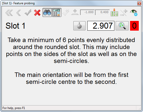
- Follow the instructions in the dialog to take at least six points from the slot, and then click OK to accept the points.
The Surface Points on the Fly dialog is displayed for the surface inspection group.
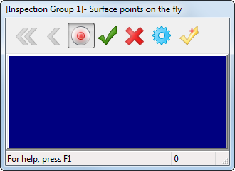
- Take a point on the irregular sloping surface on the top of the part.
PowerInspect compares it against the CAD model, and updates the dialog. For example:
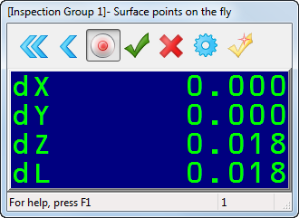
The values displayed show the distance from the point taken to the CAD surface. The dL value is the distance from the point to the nominal surface; the dX, dY, and dZ values show the deviations of the point from the nominal in the X, Y, and Z axes.
- Take at least eight points, and then click the OK button with the mouse, or press the red button on the arm to accept the points. PowerInspect returns to the CAD view, and displays a coloured spot for each point in the surface inspection. For example:
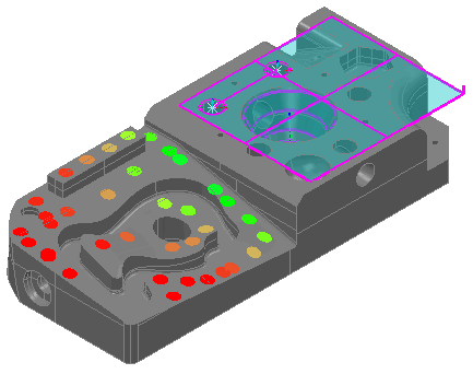
The colour of each spot indicates whether it is within the tolerance specified for the inspection group:
- Red spots are above the upper tolerance.
- Blue spots are below the lower tolerance.
- Green spots are within tolerance.
If points are out-of-tolerance, you can optimize the alignment by adding a best fit item to the inspection sequence.
- To view the measurements for each point in the inspection group, click
 to the left of the group's entry in the inspection sequence.
The sequence lists each point, its deviation and a tolerance indicator. For example:
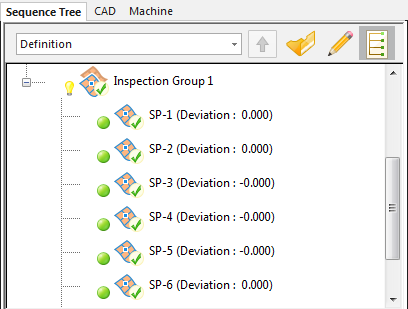
 indicates the point is above the high tolerance.
  indicates the point is below the low tolerance.
  indicates the point is within tolerance.