Inline components such as valves and reducers are placed on pipe lines.

When you place inline components from the tool palette, you can use attachment points to position them precisely on the lines.
You can reposition the component using grips. Inline components move when you move lines to which they are connected.
If you change the size of a pipe line that is attached to a reducer, the reducer automatically reorients to display with its larger size attached to the line with the larger diameter and its smaller size attached to the line with the smaller diameter.
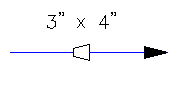
For example, if you reverse the pipe sizes here,
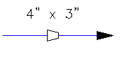
the reducer reverses its position:
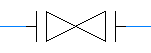
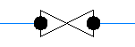
For inline components (such as valves and inline instruments), you may need to show the type of end connection or its open or closed state.
When end connections are set, the symbol automatically displays the change in the end connection. Set end connection states as follows.
| End connection states | Graphic display |
|---|---|
| Flanged |
|
| Socket Welded |

|
| Welded |
|
| Unspecified (default) |

|
If the tool palette contains a symbol for an open or closed state, the symbol automatically updates as changes are made. Otherwise, the open or closed state is reflected in the Properties palette. You can set the open or closed states as follows.
| Open or closed states | Property palette setting |
|---|---|
| Normally Open (default). Fluid can flow through without someone having to manually open a valve. Can always be set to closed. | NO |
| Normally Closed. Fluid cannot flow through. Can always be set to open, but it must be set manually. | NC |
| Lock Open | LO |
| Lock Closed | LC |
| Car Sealed Open | CSO |
| Car Sealed Closed | CSC |
If either state is set, and you need to substitute the valve (for example, if you need to change a flanged gate valve to a flanged ball valve), the substituting valve maintains the end connection and the open or closed state of the previous valve.