This tool lets you place air terminals in a project. When devices such as air terminals are placed in a view, information associated with them is used in calculating loads for the spaces (rooms) in a duct system. The rooms keep a running total of the amount of supply, return, and exhaust air supplied or removed from a room, which allows you to select the correct air terminal sizes.
Specify component elevation
- Open a view containing the duct system where you want to add an air terminal.
- Click Systems tab
 HVAC panel
 Air Terminal, and in the
Type Selector, select an air terminal type.
Air Terminal, and in the
Type Selector, select an air terminal type.
- On the ribbon, specify mode options:
- Load Family. Loads component family.
- Model in-place. Lets you create a new family of a specified component that will be available only in this project.
- On the ribbon, verify that Tag on Placement is selected to automatically add a tag. Then specify the following tagging options on the Options Bar:
If you want to... then... change the orientation of the tag select Horizontal or Vertical. load additional tags click Tags. include a leader line between the tag and the terminal select Leader. change the default length of the leader enter a value in the text box to the right of the Leader check box. - To place an air terminal directly on the face of duct, click Modify | Place Air Terminal tabLayout panel
 Air Terminal on Duct.
You can place a new air terminal on a duct, or drag an existing air terminal and place it on a duct.
- Only unhosted air terminals are supported.
- Move the cursor inside the duct to snap the air terminal to the face of the duct.
- When placing an air terminal on the side face of a duct, the insertion point is the family insertion point.
- When placing an air terminal on the end of a duct, the insertion point is controlled by the connector.
Notes:
- On the Options Bar, for non-hosted air terminal options, specify
- Rotate after placement which rotates a component after placing it in the view.
Tip: You can also press the Spacebar when placing a component to rotate it in 90 degree steps.
Some air terminals are hosted components that must be placed on a work plane.
- Rotate after placement which rotates a component after placing it in the view.
- If you selected a hosted air terminal, click
 Place on Work Plane to specify a host component.
Tip: When placing an air terminal on a work plane, it may be necessary to Pick a Plane in the Workplace dialog, or select a Placement Plane on the Options Bar when placing the component.
Place on Work Plane to specify a host component.
Tip: When placing an air terminal on a work plane, it may be necessary to Pick a Plane in the Workplace dialog, or select a Placement Plane on the Options Bar when placing the component. - Move the cursor to where you want to place the air terminal and click.
- Click Modify.
- If you are placing an un-hosted component, select the air terminal, and in the Properties palette, enter an Offset value to specify the elevation.
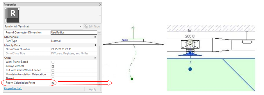
Since the room calculation point specifies which space the air terminal is in, it is also reflected in schedules. For example, if you include a column in the schedule with Space data, such as name and number, the space dictated by the room calculation point will be used.