Distributed Resistance Models
Analysis Characteristics
- Steady-state
- Three Dimensional Internal Flow
- Turbulent
- Incompressible Flow
- Distributed Resistance Models
Reference
White, F.M., “Fluid Mechanics”, McGraw-Hill, New York, 1979, pp. 305-360
Idelchik, I.E., “Handbook of Hydraulic Resistance”, CRC Press, 1994, pp. 523
Problem Description
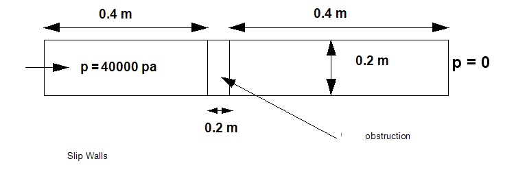
Air flows through a 3D channel with slip walls with a filter (or some flow obstruction) in the center of the channel. The pressure drop across the channel is due to only the obstruction because the walls have slip conditions.

All 4 distributed resistance models are tested:
1. Constant K factor:
K = 1.97748
At the specified pressure drop, this K factor should result in a flow rate of 0.2 m3/s.
2. Pipe friction loss:

where  is the friction factor for which we use a Blasius formula for the friction factor. L = 41.99 is the pipe length to be represented, and DH = 0.2 is hydraulic diameter of the pipe. The Blasius formula used to determine the friction factor is:

where a is 0.316 and b is 0.25. These values should result in an equivalent K-factor value of 1.97748. Hence, we can expect a flow rate 0.2 m³/s.
3. Free area ratio
For this resistance type, we use the formula from page 516 in Idelchik:

where FAR is the free area ratio. For a free area ratio of 0.62, we get a K factor of 1.9774 and thus a flow rate of 0.2 m³/s.
4. Head-loss table K factor:
We use the following table of values:
| Flow Rate (m3/sec) | Pressure Head (Pa) |
| 0.15 | 35000 |
| 0.25 | 45000 |
Geometry and Boundary Conditions

Results
| Distributed Resistance Type | Benchmark | 2018: Build 20170308 | % Error | 2019: Build 20180130 | % Error |
| Constant K | 0.2 m3/s | 0.1997 | 0.143 | 0.1961 | 1.95 |
| Pipe Friction Loss | 0.2 m3/s | 0.2171 | 8.569 | 0.1982 | .896 |
| Free Area Ratio | 0.2 m3/s | 0.1997 | 0.143 | 0.1961 | 1.95 |
| Head Loss Table | 0.2 m3/s | 0.1979 | 1.0475 | 0.1999 | .004 |