Centrifugal Pumps and Axial Fans
Centrifugal pumps and axial fans operate by converting mechanical energy from a motor into energy of a moving fluid. In a centrifugal pump, flow enters axially, is rotated through an impeller, and discharged radially after passing through a volute. The purpose of most centrifugal pumps is to increase the pressure of a liquid or cause it to flow through one or more pipes.
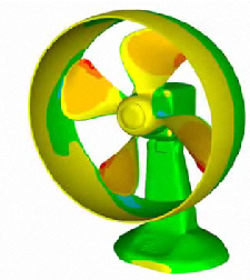
In an axial fan, air is accelerated as it passes through a rotating impeller composed of several blades. The purpose of most axial fans is to increase the air velocity, often for ventilation purposes.
Objectives
Most pump and fan applications focus on determining the operating point for a given condition:
- Determine the run-out flow rate (at 0 head loss)
- Determine the flow rate for a given head loss
- Determine the head for a given flow rate
- Determine the head-capacity curve (performance characteristic)
Another objective is to determine the source of inefficiencies in the flow. These may be due to recirculation areas within the suction side of the blade passage or a jet-wake pattern near the impeller outlet.
Application Examples

- Water pumps
- Cooling fans (axial flow)
- Cooling fans (radial flow)
Modeling Strategy
Error-free CAD geometry without extraneous features is essential to analysis efficiency. Remove small edges and sliver surfaces, particularly on the impeller and volute casing. Close small gaps around wear rings and packing.
Extend the suction (inlet) and discharge (outlet) at least 3-4 hydraulic diameters from the impeller. This is necessary to prevent the boundary conditions from directly influencing the results.
The rotating region should just envelop the impeller, but not touch any static parts.It should extend halfway between the outer diameter of the impeller and the cutwater. Click here for more rotating region guidelines...
To facilitate local mesh refinement around blade leading edges and the volute tongue of a pump housing, try to construct them using distinct surfaces (instead of large surfaces that extend over a the expanse of the blade or volute). This makes it much easier to apply local mesh refinement to these critical regions.
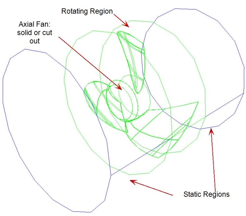
The typical model configuration for axial fan models consists of the impeller surrounded by a cylidrically-shaped rotating region. Extensions are added to the inlet and outlet, and extend 3-4 hydraulic diameters from the rotating region:
Analysis Set up
Materials
Create and assign a rotating region material to the volume surrounding the impeller. On the Material Editor, set the Scenario type to Known Rotational Speed. Specify the rotational speed using a table, and increase from 0 to the full speed over 50 time steps.
Example:
- If a five bladed turbine rotates at 3000 RPM, the blade-pass time step size is the time required to rotate 72 degrees (360 / 5 = 72).
- At 3000 RPM, this works out to a time step of 0.004 seconds. (D / N x 6 = 72 / (3000)x(6) = 0.004)
- The time needed to achieve full rotational speed over 50 time steps is 0.2 seconds. (50 x 0.004 = 0.2 seconds.) The values of the rotational speed table are:
| Impeller Speed(RPM) | Time, sec |
| 0 | 0 |
| 3000 | 0.2 |
| 3000 | 100 |
Boundary Conditions
Specify Pressure = 0 at the suction inlet.
The outlet condition is determined by the objective of the analysis:
- To determine the run-out flow rate: Specify Pressure = 0 at the discharge.
- To determine the flow rate at a given head: Specify a transient pressure condition at the discharge. Use a piecewise linear distribution to vary the pressure from 0 to the target value over 100 time steps.
- To determine the head at a given flow rate: Specify a transient volume flow rate at the discharge. Use a piecewise linear distribution to vary the flow rate from 0 to the target over 100 time steps. To assign the flow direction out of the model, specify negative flow values in the table.
Mesh
- Unless heat transfer is relevant, suppress solid parts such as the impeller, volute casing, and wear rings.
- Define the mesh distribution using either Automatic-Sizing or Manual Sizing.
- Automatic sizing creates a distribution based on the curvature of the geometry. It strives to blend mesh gradients across the entire model. Use the Use uniform setting on the rotation region. This prevents artificial gradients in the flow due to mesh size variations
- Alternatively, use manual mesh sizing. The typical strategy is to assign element sizes to parts based on their size, and to refine using surface and edge sizing.
- The following considerations apply for both mesh strategies:
- A fine enough mesh density is critical to a successful analysis. Because of the high flow gradients in a rotating device, it is essential that the mesh be fine enough to resolve them.
- Refine the mesh locally on vane leading edges and volute tongues to ensure the curvature is adequately represented. These are typically critical areas and are where large pressure and flow gradients occur.
- Check the mesh distribution on the suction side of each passage. An adverse pressure gradient often occurs in this region, and it is essential that enough mesh exist to adequately resolve the flow gradients.
- Ensure that nodal aspect ratios within the rotation region are below 100. To check aspect ratio, enable Stream Function in the Result quantities dialog, and run 0 iterations. Create an iso surface to visualize Nodal Aspect Ratio.
Monitor Points
Create a monitor point at the center of the outlet to monitor pressure and flow rate (multiply the velocity by the outlet area).
To do this:
- Right click off the model, and click Monitor points from the menu.
- Position the point, and click Add.
Running
Time Step Size and Number of Time Steps to Run
Because of the rotational speed and boundary condition ramp-up, it is important to run enough time steps to properly start the flow and then to run it out a sufficient number of revolutions to achieve fully-developed flow. A good guideline is to run the analysis in three phases:
Phase 1: Ramp up the rotational speed and boundary conditions.
Phase 2: Run 20 complete revolutions to achieve fully-developed flow using a time step equal to a single blade pass interval.
Phase 3: Run 1 revolution using a time step equal to the passage of 3 degrees. This final revolution ensures that the flow, pressure, and hydraulic torque have reached steady-state.
Some planning and simple calculations are required to determine the correct time step sizes and the number of time steps to run for each phase. An easy way to illustrate this is through an example:
Example
A five-bladed impeller rotates at 3000 RPM. The blade-to-blade time step size is 0.004**seconds**. t = D / N x 6. (D = 360 / number of blades; N = RPM); t = 72 / (3000)x(6) = 0.004s
Phase 1:
- The rotational speed requires 50 time steps to ramp up. This is 0.004 x 50 = 0.2 seconds.
- The outlet boundary condition requires an additional 50 steps. This is 0.004 x 50 = 0.2 seconds.
A total of 0.4 seconds and 100 time steps have elapsed.
Phase 2:
- At full speed, 20 complete revolutions requires an additional 100 steps. (at 1 time step per passage, it takes 5 steps per revolution, resulting in 100 steps to rotate 20 revolutions). This is another 0.4 seconds.
An additional 0.4 seconds and 100 additional time steps have elapsed.
Phase 3:
The time step to rotate 3 degrees per time step is 0.000167 s. (t = 3 / N x 6 = 3 / (3000) x (6) = 0.000167seconds)
- At 3 degrees per time step, 120 steps are required for one revolution
For phase 3, an additional 0.02 seconds and 120 steps have elapsed.
To summarize:
| Time Step Size | Number of time steps | |
| Phase 1 | 0.004 s | 100 |
| Phase 2 | 0.004 s | 100 |
| Phase 3 | 0.000167 s | 120 |
Results Extraction
To view the time history of hydraulic torque, click Results (tab) > Review (expanding panel) > Rotating Region Results. This data is also saved to an external "csv" file in the folder containing the scenario, and can be graphed by importing into Excel.
Track the solution progress using the Monitor Point created at the outlet. This provides a focused view of the solution progress at a critical area.
To animate graphical results:
- Set the time step to half of a blade pass.
- Set the Save Interval (on the Solve dialog) to 1.
- Continue the analysis, and run enough time steps to complete a complete revolution.
To compute a head-capacity characteristic curve:
- Set up and run one operating point.
- Clone the scenario, and change either the outlet flow rate or pressure rise. Run...
- Repeat step 2 for the remaining operating points.
- Create a cut plane at the outlet, and make it a summary plane.
- On the Decision Center, right click on the Summary Plane branch, and click Update critical values.
- In the Output bar, make sure the Summary Plane tab is showing. Click the Save button.
- The data is saved in a "csv" file. Open in Excel, and plot the Pressure and Flow Rate for all the scenarios.
Things to avoid
Avoid not defining an adequate mesh. Rotating analyses are typically more sensitive to mesh distribution than static analyses. Make sure high gradient areas such as blade leading edges, the volute tongue, and the suction side of the blade passage are adequately meshed.
Avoid the impulsive start-up. This is when the full rotational speed is specified from the beginning of the analysis. It is a condition to be avoided because it is not physically real, and can lead to separation regions in the blade passages. Alternatively, gradually increase the rotational speed of the rotating region using a table definition as described above.
Avoid direct application of non-zero pressure or flow rate at the discharge. Gradually increase the exit condition as the rotational speed ramps up. Failure to do this will result in flow going the wrong way through the pump.