Configuration 3: Ceiling-mounted Luminaire
Another common lighting configuration is the ceiling-mount. Examples include chandelier, track-lighting, and hanging fixtures.
The Ceiling-mounted simulation configuration is based on the guidelines provided in the UL1598 test procedure for the surface-mount and recessed luminaire configurations. To simulate the natural convection and temperature distribution, immerse the test ceiling within a volume of air. There are several ways to construct the test box, based on the desired level of fidelity with physical testing. The amount of detail in the wall test box model determines how much heat is conducted to the wall.
For Surface Ceiling Luminaires, the three options are an adiabatic ceiling, a solid test box, and the UL Test box. For Recessed Luminaries, the two options are a solid test box and the UL Test box.
Ceiling Luminaire Geometry
The analysis region should be constructed based on the configuration of the text fixture. For each configuration, construct a volume of air around the fixture to simulate air movement due to natural convection and heat transfer.
There are several ways to simulate a Surface Ceiling Luminaire based on the desired fidelity with experimental results:
Adiabatic Setup: Surface Ceiling
Suppress the ceiling part so that it is not meshed. This prevents heat from being conducted through the ceiling, which creates an adiabatic mounting surface for the fixture. This approach simulates a "worst case" situation in which heat is only removed through natural convection. Use this configuration to quickly simulate design options for comparative studies.
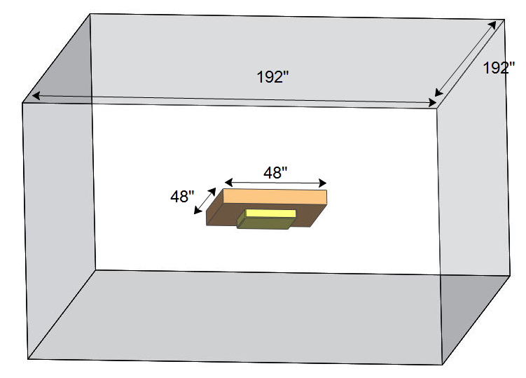
Attach the fixture to the center of a void with dimensions 48” x 48” x 6.75”.
Do not include the junction box or luminaire mounting bracket as these details have little impact on the results, and increase mesh size and run time.
The air volume surrounding the wall and fixture should extend the following dimensions:
- 192" x 192" square
- 72" above the top of the void that represents the ceiling.
- 32" below the bottom of the luminaire.
 |  |
Hardwood Setup: Surface Ceiling
This configuration allows heat to conduct from the fixture and convect into the surrounding air. While this setup does not replicate a physical installation, it does remove the unknown thermal sink performance of the wall, and mimics the UL thermal test strategy within a temperature-controlled chamber.
- Attach the fixture to the center of a wooden block with dimensions of 48” x 48” x 6.75”.
- Do not include the junction box and luminaire mounting bracket as these details have little impact on the results, and increase mesh size and run time.
- Assign the hardwood material from the Default Material Database.
The air volume surrounding the wall and fixture should extend the following dimensions:
- 192" x 192" square
- 72" above the top of the ceiling block.
- 32" below the bottom of the luminaire.
| | |
UL Test Setup: Surface Ceiling
The UL Test Setup uses the same dimensions as the Hardwood configuration, but uses the UL Test box instead of the solid wood base. Use this test configuration to closely mimic physical testing.
Construct the wall test fixture as specified by the UL 1598 specification:
- The face and back should be 48 inch square plywood.
- The sides should be 2 x 4 in wooden members.
- The ends should be 1 x 4 in wooden members.
- The inside supports should be 2 x 4 in wooden members:
Simplify the octagonal junction box in CAD to remove all of the sheet metal detail.
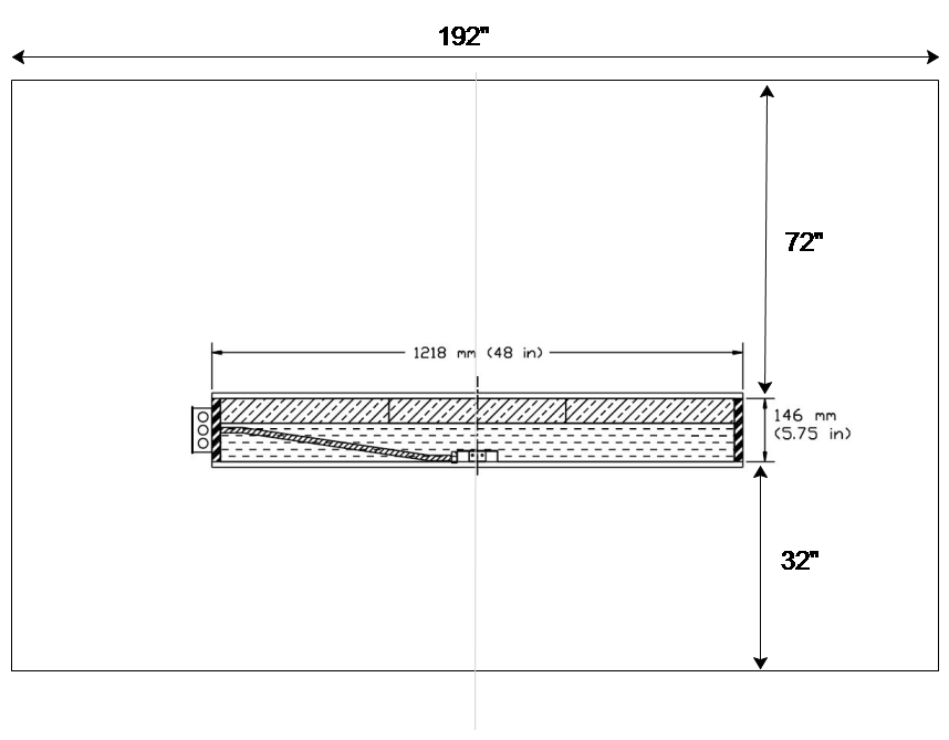
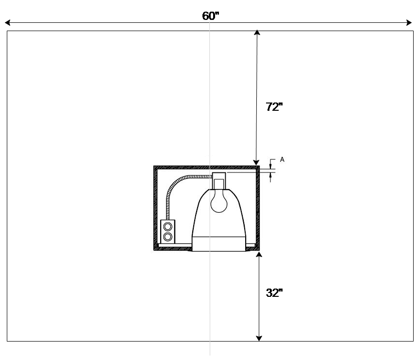
Enclose the test fixture in a volume of air. The air volume surrounding the text fixture should extend the following dimensions:
- 192" x 192" square
- 72" above the top of the ceiling block.
- 32" below the bottom of the luminaire.
UL Test Setup: Recessed Ceiling
The recommended way to simulate a Recessed Ceiling Luminaire is with the UL Test Setup for a recessed ceiling. The UL Test box uses this test configuration to closely mimic physical testing.
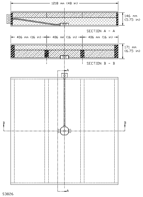
Construct a CAD model of the test fixture based on the guidelines described in the UL 1598 specification. Use half inch plywood, and half inch clearances (dimensions A and B, below). The upper drawing shows a top view. The lower drawing shows a side view:
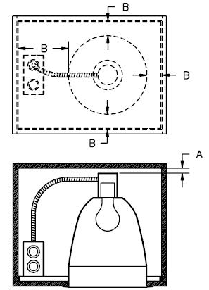
Simplify the sheet metal in the luminaire model to remove small radii, formed features, and corner gaps as they increase the mesh size and solve time but do not improve the flow and thermal solution.
Construct a volume of air around the fixture to simulate air movement due to natural convection and heat transfer:
SBoundary Conditions
- To define openings at the top and bottom, assign Static Gage Pressure = 0 to both surfaces
- Bottom face (inlet): Static Temperature = ambient temperature
- Heat loading is specific to the lighting type. Click for LED. Click for fluorescent.