Heat Exchanger Modeling Guidelines
Heat exchangers and air conditioners are common elements in AEC, Data Center, and other architectural applications, and play a significant role in their thermal management. Proper simulation of both is essential for optimizing thermal behavior. The following guidelines describe effective use of the Heat Exchanger material model.
Build the heat exchanger (1) so that it is not immersed within the system (2)
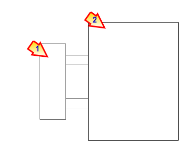
Construct a volume at the inlet (1) and outlet (2) to offset the device from the system

The heat exchanger should not touch the system. The material of both extensions should be the system working fluid.
Construct the inlet (1) and outlet (2) with a single, separate, planar surface
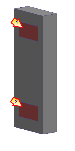
Openings consisting of multiple surfaces are not supported.
At the conclusion of the simulation, the Heat exchanger openings are listed in the Summary file as system openings:
- Heat exchanger inlets appear as a model outlets (pressure = 0).
- Heat exchanger outlets appear as a model inlets (volume flow rate).
CRAC units
When simulating data center CRAC units, it is not always feasible to build the device completely outside of the system (as shown above).
A good technique is place the heat exchanger device (1) inside of the CRAC unit (2), and suppress (don't mesh) the CRAC unit part.
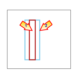
The heat exchanger device does not touch the mesh on the system (except at the inlet and outlet). This satisfies the requirement that the heat exchanger not be immersed within the system.
For an example of defining a heat exchanger device in a CRAC, click here.
Considerations and Limitations
- The Heat Exchanger material device is specifically designed to simulate closed-loop heat exchanger devices. It does not support open-loop systems (energy recovery and recapture of conditioned air).
- If your model contains multiple heat exchanger devices, assign each one individually. Do not assign a heat exchanger material to more than one part at a time.
- Do not assign any flow or thermal boundary conditions to the heat exchanger part.
- The heat exchanger material device cannot transfer more heat than allowed by specified physical constraints on the model.
- A uniform pressure condition is automatically applied at the heat exchanger inlet. For this reason, do not locate heat exchanger devices in pressurized areas. This can cause excessive flow to be drawn into the heat exchanger device.
- The simulation model must contain at least one flux-based heat transfer boundary condition. Examples include Heat Flux, Total Heat Flux, Film coefficient, and Radiation. If the model only contains Temperature boundary conditions and Heat Generation conditions, the Heat Exchanger device does not affect the temperature within the model.