Meshing Lighting Applications
A basic guideline for a high-quality analysis model is that the mesh distribution is sufficient to resolve the flow and temperature gradients efficiently. In regions where the flow circulates or experiences large gradients (such as in wakes, vortices, and separation regions), a finer mesh is required.
Automatic Sizing
For most models, use Autosizing to define the mesh distribution. It may be necessary to locally refine the mesh on geometric features that are highly detailed. For more information about Mesh Autosizing and model preparation...
In some cases, it may be necessary to adjust the Minimum Refinement Length to reduce their effect on the overall mesh count.
To locally refine the mesh in high-gradient flow regions, adjust the mesh distribution on geometric volumes and surfaces.
Mesh Refinement
If there are no appropriate geometric features in a particular region, create a mesh refinement region. There are two primary ways to do this:
Add volumes for refinement in the CAD model
If the air volume is built in the CAD model, one strategy is to construct refinement regions directly on the model.
A simple method is to cut out a region near the fixture, resulting in a void:
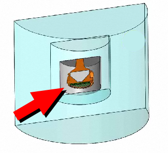
When the model is transferred into Autodesk® CFD, the void is automatically filled.
Assign a material, and refine the mesh distribution within the region to focus mesh on the geometric details of the fixture and surrounding flow.
Build refinement regions in Autodesk® CFD
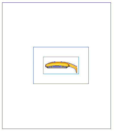
After assigning the mesh in the Meshing task, left click off the model, and click the Refinement Region icon:
![]()
Position the region around critical components and in areas where large flow and temperature gradients are expected.
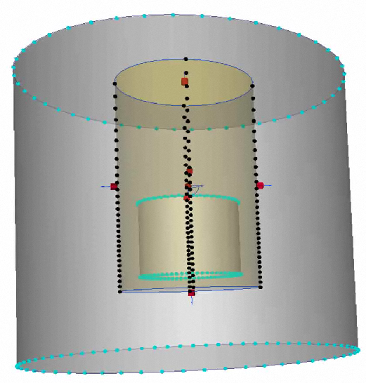
- If the model (and flow) are oriented vertically, extend the refinement region to the outlet of the enclosure. This captures the high-velocity and high-temperature region above the lighting fixture.
- On the Refinement region dialog, uncheck the Uniform box to allow the mesh distribution to vary within the region.
- A slider value from 0.75 to 0.9 is appropriate for most applications.
Example:
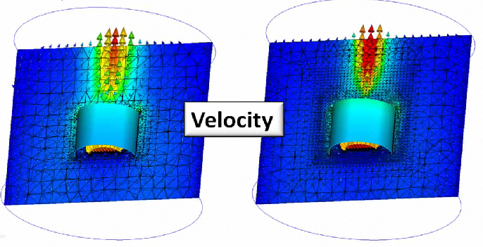
A refinement region is built around a fixture. The influence on the velocity near the fixture and in the thermal plume is significant:
The influence on the temperature field is also significant:
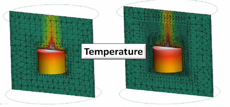
Capturing these gradients is essential for the accuracy of the solution.
Nested Regions
An extension of this technique is to nest multiple regions around the device. Create these regions in the CAD model as Refinement Regions in the Autodesk® CFD Mesh task do not support this technique. This concept is illustrated:
The mesh distribution in the inner-most region is the finest, and focuses the mesh where the gradients are highest. Because this region is small relative to the calculation domain, this high-density mesh does not propagate far, which keeps the overall mesh count from getting too big. The mesh distribution in the second nested region is a little more coarse, and the mesh in the remainder of the domain is even coarser. This approach efficiently concentrates elements only where they are most needed, providing an efficient use of meshing and solving resources.
Additional Meshing Tools
There are several additional meshing tools that are very useful for lighting applications:
Adaptive Meshing
Since its introduction, Automatic Mesh Sizing has greatly simplified the modeling process. Automatic Mesh Sizing defines a mesh that is optimized for the model and accurately represents every detail of the geometry.
A good representation of the geometry is only one requirement for a high fidelity solution. For example, the flow on a simple model with a uniform mesh can contain significant gradients. The results on the coarse mesh may not be highly accurate, but they do indicate flow trends. These trends can be used to identify where the elements should be concentrated to improve solution accuracy.
Mesh Adaptation uses solution results to progressively improve the mesh definition. The simulation is run several times. Each time the results in the previous cycle are used to improve the mesh in the next cycle. The result is a mesh that is optimized for the particular simulation. The mesh is finer for high gradient regions, and coarser elsewhere.
When Mesh Adaptation is enabled, the following occurs:
- A baseline scenario is run to completion.
- The mesh is changed (often refined) based on velocity, pressure, and temperature (if available). The simulation is run to completion.
- The process repeats for each Adaptation cycle.
The result is an intelligently refined mesh that is tuned for the flow and temperature results fields.
For more about Adaptive Meshing...
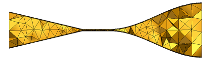
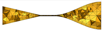
Volume Mesh Growth Rate
Adjust the Volume Mesh Growth Rate when there are large regions containing sparse geometric detail. High gradient flows in such regions often require a finer mesh than the default settings can produce.
When the Volume Mesh Growth Rate is controlled, an alternative meshing scheme in invoked. The resultant model size is usually larger than that produced by the default mesh settings, but the resultant mesh will generally improve analysis results.
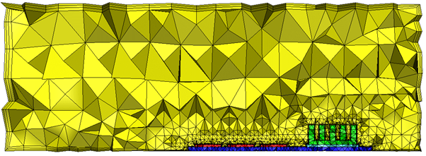
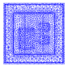
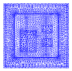
Examples
Default volume growth rate:
Modified volume growth rate:
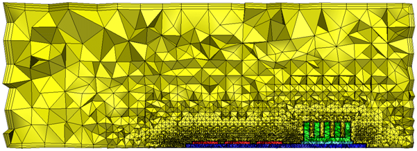
When the Volume Growth Rate is modified, the element growth is more gradual in the open area of the channel. This is ideal for calculating swirl and other flow and temperature gradients.
Workflow for volume growth
- Apply Automatic sizing. (Click Autosize on Automatic Sizing context panel.)
- Click the Advanced button.
- Check the box for Volume growth rate.
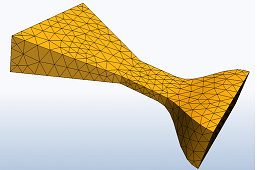
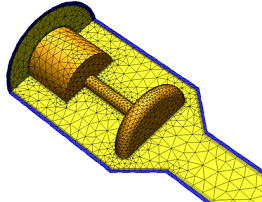
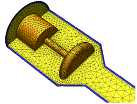
Improved Surface and Boundary Layer Meshing
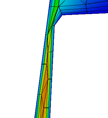
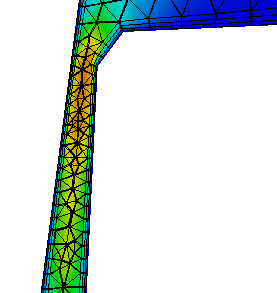
Because default Automatic Sizing bases the mesh distribution on edge and surface curvature, it often creates a mesh that is too coarse on surfaces that are flat. Likewise, Automatic Sizing often produces a coarse mesh in regions that are not closely bounded by geometry. Automatic Refinement eliminates these problems by providing better control over how elements grow from the walls into large, open regions. While the resultant mesh count may be higher, the solution accuracy is generally improved.
- Automatic Refinement produces a better mesh on surfaces with little curvature or with few edges.
- Automatic Refinement varies the mesh enhancement layer thickness based on the local mesh.
Automatic Refinement is only available for 3D Acis- (including Inventor), Parasolid-, and Granite (Pro/Engineer)-based models.
Examples:
Standard Autosizing | Automatic Refinement |
 |  |
 |  |
 |  |
|
|
|
Workflow for surface refinement
- Apply Automatic sizing. (Click Autosize on Automatic Sizing context panel.)
- In Automatic Sizing Refinement, check Surface refinement.
- Click Refine.
- To achieve greater mesh control for external flow simulations, enable Volume-based Autosizing. Do this by changing the value of the mesh_volume_autosize flag to 1 in the Flag Manager.
- The default settings produce a high quality, efficient mesh for most models. Based on analysis expectations, however, changes may be required to fine-tune the mesh. Click the Advanced button near the bottom of the dialog, and modify the Surface growth rate and Enhancement growth rate.
- Close the Advanced dialog, and click the Refine button again.
To disable Automatic Refinement, uncheck Surface refinement.
Notes:
There are several flags that control the behavior of the volume mesh:
- mesh_volume_autosize: To force a finer mesh in regions that are not closely bounded by geometry, such as in many external-flow simulations, enable Volume-Based Autosizing. This additional refinement better controls how elements grow from the walls into large, open regions. While the resultant mesh count may be higher, the solution accuracy is generally improved. To enable Volume-Based Autosizing, change the value of this flag to 1 in the Flag Manager.
- mesh_volume_autosize_growth: Volume-based autosizing grows the mesh by no more than 35% from the sizes prescribed at the surface and edges. To change this value, use this flag. Set the growth rate within the domain (specified as integer percent). Default 135 (i.e. 1.35).
- mesh_volume_error_tol: In general, volume autosizing result in a less refined surface mesh but a better volume transition. Small error tolerances best duplicate the level of surface refinement of a surface autosized mesh. The recommended range is from 5 to 15; the default is 12. Smaller values respect the surface/edge length scales to a greater degree.
Gaps and Thin Solids
Gap Refinement controls the mesh within gaps between closely oriented surfaces, even if they belong to different parts.
- It meshes critical gaps with a fine mesh, and smaller, less relevant gaps with a coarse mesh.
- It improves the accuracy in small clearances and the heat transfer in thin solids.
- By focusing mesh in essential gaps, it improves solution accuracy and performance.
- Gap Refinement ignores flow openings (pressure, velocity, etc). If you have two openings with a small gap between them, Gap Refinement does not modify the elements in the gap. Mesh Adaptation can help in these situations.
Gap Refinement Meshing is only available for 3D Acis-, Parasolid-, and Granite (Pro/Engineer)-based models.
Examples:
Default Autosizing:
This mesh in the gap is very coarse:
Gap-Refinement:
This mesh in the gap is significantly better:
Workflow for gap refinement
- Apply Automatic sizing. (Click AutoSize on the Automatic Sizing context panel.
- In Automatic Sizing Refinement, check Surface refinement.
- Check Gap Refinement.
- Click Refine.
- The default settings produce a high quality, efficient mesh for most models. Based on analysis expectations, however, changes may be required to fine-tune the mesh. Click the Advanced button near the bottom of the dialog.
- After modifying settings, close the Advanced dialog, and click the Refine button again.
To disable Gap Refinement, uncheck the Gap Refinement box.