Combined Linear-Angular Motion
In Combined Linear/Angular motion, the object translates linearly along the path specified on the Motion task dialog. The instantaneous linear position of the object is determined either by user-specification or as a result of flow-induced forces.
As the object translates, it will also rotate about a user-specified axis. The direction of rotation is either determined by the user or is a result of flow-induced forces. For flow-induced rotation, developed torque is used to compute angular accelerations.
If both motions are flow induced, it is assumed that the two motions are uncoupled and work independently. The linear translation equations update the center of rotation over time and the rotation equations update the directional cosines over time, thus yielding a combined motion.
The location of the axis of rotation is determined by the translation of the object. Conversely, the direction of translation is not affected by the rotation. (This kind of motion is implemented using the Sliding Vane motion type, described later in this chapter.)
Examples of combined motion include an object sliding along a path and rotating about its center axis. The center of rotation is translating with the object:
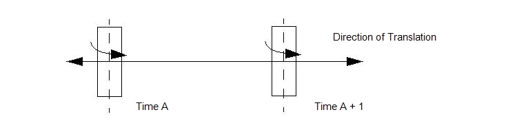
Another example is an oscillating piston whose axis of rotation is its direction of travel. This is a typical configuration found in many flow meters.

The two elements of Combined motion, Linear and Angular, are defined independently as User-prescribed or Flow-driven. The Flow-Driven check boxes on the Motion task dialog govern how each element is defined on the Material Editor. The possible combinations of user-prescribed and flow-driven are listed:
- User-Linear/User-Angular
- Flow-Linear/User-Angular
- User-Linear/Flow-Angular
- Flow-Linear/Flow-Angular
The following sections describe how to set up User-prescribed and Flow-driven motions. The variation methods described are applicable to the two user-defined/flow-driven combinations: