Assigning Combined Linear-Angular Motion
- Select one or more objects.
- To open the Motion quick edit dialog, click Edit on the Motion context panel.
- Select Combined Linear/Angular as the Type.
- Specify if the Linear motion is Flow Driven.
- Specify if the Angular motion is Flow Driven.
- Click Edit... on the Edit Motion line. This opens either the User Defined or Flow Driven Motion Editor. Define the motion properties.
- Specify the Linear Motion Parameters.
- Specify the Angular Motion Parameters.
- Click Apply.
Linear Motion Parameters
Direction Vector
Either key in a vector or use the pop-out to set the direction of travel of the object.
Choose the Global X, Y, or Z axes to choose a Cartesian direction as the motion direction.
To graphically set the direction, click the Select Surface button, and select a surface. The motion direction will be normal to the selected surface.
Click the Inverse button to switch the direction.
An example of assigning linear direction:
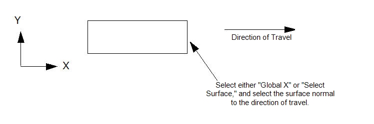
The specified direction of travel is the reference direction, and all directional-dependent parameters are relative to it. Specified positive displacements will move the object in the reference direction. Negative displacements will move the object in the opposite direction.
Flow-driven parameters such as driving forces and resistive forces reference this direction as well. Positive values of a driving force will act in the direction of the Direction Vector; negative values will act in the opposite direction. In contrast, positive resistance forces will act in the opposite direction of the Direction Vector; negative resistance forces will act in same direction as the Direction Vector.
Initial Position
Either key in a value or use the pop-out slider dialog to modify the initial position of the object from the as-built location in the CAD model. This is very useful for fine-tuning the model if the position of the object in the CAD is different from the true starting position.
The positive direction of adjustment is in the Direction of Travel. Use the slider to move the object in the Direction of Travel in both the positive and negative directions.
Linear Minimum and Maximum Bounds
Use the Minimum and Maximum fields to set the bounds of motion for flow-driven motion. (This is only required, and available, for flow-driven motion.) Bounds can be set by keying in a bounding position or using the slider to graphically set the position. The default state is that the motion is unbounded.
- To key-in a location in the field, click in the field, and specify the desired coordinate. For example, if 1.5 inches is entered as a minimum value, then the object can not go beyond 1.5 inches in the negative direction of travel. This distance is relative to the initial position of the object.
- To specify the value graphically, use the pop-out dialog to position the plane at the desired boundary with the slider. The graphical plane moves normal to the direction of travel. All locations are relative to the initial position.
The Min and Max boundaries can be specified using different methods.
Angular Motion Parameters
Axis of Rotation
Either key in a vector or use the pop-out to set the axis of rotation. The rotational direction uses the right hand rule convention.
Choose the Global X, Y, or Z axes to choose a Cartesian direction as the axis of rotation.
To graphically set the direction, click the Select Surface button, and select a surface. The axis will be normal to the selected surface.
For example:
If the desired axis of rotation is the Global Z, and the rotation direction is positive, do one of the following:
- Enter a unit vector of 0,0,1, or
- Open the pop-out dialog box, and click the Z button, or
- Select the surface normal to the Z axis.
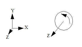
The Direction of Rotation is the reference direction for all directional-dependent parameters. For user-prescribed rotation, a positive angular rotation will rotate the object in the Direction of Rotation. A negative angular rotation will rotate the object in the opposite direction.
Flow-driven parameters such as driving torque and resistive torque reference this direction as well. Positive values of a driving torque will act in the direction of the Axis of Rotation; negative values will act in the opposite direction. In contrast, positive resistance forces will act in the opposite direction of the Direction Vector; negative resistance forces will act in same direction as the Direction Vector.
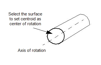
Center of Rotation
The center of rotation is the point through which the axis of rotation passes. There are two ways to specify it: as the centroid of a selected surface or by keying-in coordinates.
To specify the centroid of a surface, open the pop-out, click the Select Surface button, and select the surface.
The axis of rotation will pass through the centroid of the selected surface:
Initial Angular Position
Modify the initial angular position from the location as built in the CAD model. This is very useful for fine-tuning the model in case the as-built initial position is not quite correct.
The positive direction of adjustment is in the direction defined by the Axis of Rotation. Either key in an angular value or use the slider on the pop-out dialog to rotate the object about the axis of rotation in both the positive and negative directions.
Angular Minimum and Maximum Bounds
Use the Minimum and Maximum fields to set the bounds of rotation for flow-driven angular motion. (This is only required, and available, for flow-driven rotation.) Bounds can be set by keying in an angular bounding position or using the slider on the pop-out dialog to select an angular position. The default state is that the motion is unbounded.
The minimum and maximum boundaries can be specified differently, if necessary. Note that the bounds are relative to the initial position specified with the Initial Position Slider.