If, during structure design a section of an RC beam/continuous footing has not been defined (in the Sections dialog box), a cross section of a designed beam/continuous footing is to be assigned in the RC beam design module. It is possible by:
- selecting the 'Section Type' icon
 or
or - selecting the command: RC element / Cross-section Type from the menu.
The dialog box shown below will be displayed on the screen.

The above dialog box is used to:
- Select the section type of a beam/continuous footing (rectangular, T-section, I-section, T-section with lowered slabs) and set the section dimensions;
- Define section name; the program assigns by default a section name consisting of several letters that denote section type and dimensions of its cross-section (change in the dimensions of the cross-section of a profile are accounted for in the section name).
- Set the beginning and end of the beam/continuous footing segment, to which a section is to be assigned;
- Set the beam segment sequence;
- Define the tapered section of the beam and set the segment location on the beam.
The following four section types of a beam/continuous footing are available: rectangular, T-section, I-section and T-section with lowered slabs. Dialog box contents (parameters) vary according to the selected type. The above dialog box contains rectangular section parameters (similar parameters are available for the T-section type).
Once the third or fourth section type is selected, the dialog box will contain two additional tabs: Slabs and Cuts.
During the cross section definition, the following options are available:
- Label - field for entering the label - for structure identification (optional). Define section name; the program assigns by default a section name consisting of several letters that denote section type and dimensions of its cross-section (change in the dimensions of the cross-section of a profile are accounted for in the section name).
- Start - edit field for setting coordinates of the beginning of the span segment, to which the section will be assigned. Apart from numerical values, characteristic points (span beginning / end, beam beginning / end) can be specified there. These points can be entered using the keyboard or selected from the list in the box.
- End - Edit field for setting coordinates of the end of the span segment, to which the section will be assigned. Apart from numerical values, characteristic points (span beginning / end, beam beginning / end) can be specified there. These points can be entered using the keyboard or selected from the list in the box.
Cross section dimensions are to be entered in the Basic Dimensions field.
Buttons: '<<' and '>>' located in the lower part of the dialog box allow to switch between the previous and the next beam's span.
The bottom part of the dialog box contains the Advanced button. Pressing the button results in opening the dialog box for defining additional parameters (among other things, splice reinforcement parameters).
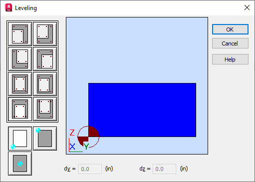
The Leveling button is used to set the segment sequence on the beam. Location of a given segment is described with regard to the foregoing one.
Once the segment is selected and the Leveling button is pressed, the Leveling dialog box will appear on the screen (see the figure below). It aids in setting the segment location by using characteristic section points (e.g. colinearity with regard to the right upper corner of the section). Otherwise, section leveling can be set by entering the segment displacements with regard to 'dy' and 'dz'. The leveling reference point can be set arbitrarily. The segment can be leveled in two directions: Y and Z. The 'dy' and 'dz' fields show the displacement increment for the characteristic points in relation to the reference point. Changing the reference point results in automatic recalculation of 'dz' by 'dy'. The section displayed in gray corresponds to the selected segment, while the yellow section stands for the adjoining segment (the reference segment for leveling).

Once the Use Tapered Section option is active, a linearly varying cross section type can be assigned by entering the value of the height of the right edge of the selected segment in the h2 field. Note: for the left cantilever, h2 corresponds to the left edge of the segment.
Additionally, using the Edge Section Location button, the location of edge sections of the selected segment can be defined. The mechanism is the same as for the Leveling option.