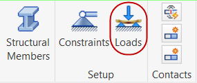
- Click Autodesk Nastran
 Setup
Setup Loads.
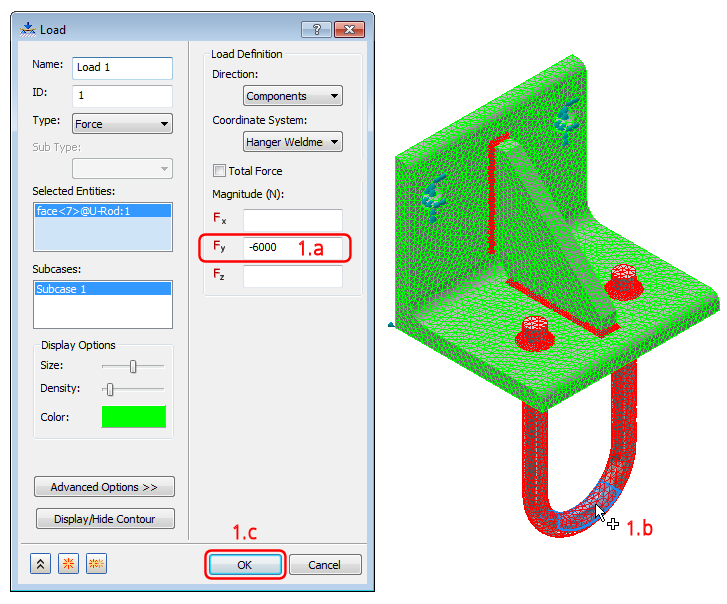
Refer to Figure 1.a – 1.c for the following three steps.

Figure 1.a – 1.c
- Type –6000 in the Fy field under the Magnitude (N) heading.
- Select the top half of the curved cylindrical surface at the center of the U-Rod bend, as shown in the preceding figure. The CAD model surface was split to provide a +/- 45° load application zone. This 45° load zone surface was then split once again so that the load could be applied only to the top half of the rod circumference.
The clicked face is added to the Selected Entities list.
- Click OK to apply the load and exit the dialog box.
- Verify that you have applied the load correctly by comparing your browser and model appearance to the following image:

| Previous Topic: Apply the Constraints | Next Topic: Run the Analysis |