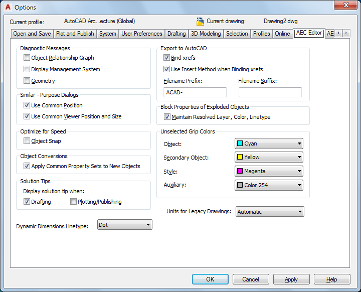
Use this procedure to specify settings to control the display of diagnostic messages and solution tips, placement of dialog boxes and viewers on the screen, and whether objects retain their properties exported to an AutoCAD or DXF file.
To improve drawing performance, you can limit the snap points provided by certain display representations, and decrease the layer loading time of the Layer Manager.
You can also specify settings for grip colors, and specify whether dynamic dimensions appear when you select and move grips to change the geometry of an object.
The AEC Editor settings that you specify are saved in the Windows® registry.
- Click

 .
. - Click the AEC Editor tab.

Specifying default AEC Editor options for the current drawing
- Under Diagnostic Messages, select options for displaying diagnostic messages on the command line:
If you want to… Then… display data about the relationship between objects in the drawing select Object Relationship Graph. display Display System errors select Display Management System. display object geometry-specific data select Geometry. All diagnostic messages are off by default.
- Under Similar-Purpose Dialog Boxes, select options for the default position of dialog boxes and viewers:
If you want to… Then… use a common position on the screen for similar dialog boxes select Use Common Position. Some dialog boxes, such as those containing style properties, are always displayed in the center of the screen, regardless of this setting. use a common position for similar-purpose viewers select Use Common Viewer Position and Size. Some viewers are not controlled by this setting. - Under Optimize for Speed, select Object Snap to limit certain display representations to respond only to the Node and Insert object snaps.
This setting affects stair, railing, space boundary, multi-view block, masking block, slice, and clip volume result (building section) objects.
- Under Object Conversions, choose Apply Common Property Sets to New Objects if you wish to have common property sets automatically applied to new objects when applying tool properties.
When you apply the properties of a tool to an object in the drawing, the result can often be a new object. For instance, when you apply the tool properties of a door to an existing window, a new door object is created in place of the existing window. With this setting enabled, any property sets that were assigned to the existing window will automatically be preserved and applied to the new door provided that the property set definitions in question applies to both types of objects (in this case, both doors and windows are selected on the property set’s applies to tab).
- Under Solution Tips, specify whether you want solution tips to be displayed during the listed activities. Drafting is selected by default. Plotting/Publishing is cleared by default.
- Under Dynamic Dimensions Linetype, select either Continuous or Dot.
The dimensions identify the current value of the dimension being edited, such as the length of a wall, the difference between the current value and the new dimension based on the position of the grip, and the total value. For example, when you select and move a Lengthen grip on a wall, the dimensions shown are the current length, the difference between the current length and the length based on where you moved the grip, and the total new length of the wall.
The dynamic dimensions will display in either continuous or dot linetype based on your selection.
- Under Export to AutoCAD, select Use Insert Method when Binding xrefs if you want all objects from an xref drawing referenced in the file you export to be incorporated into the host drawing.
If you select this option, the names of the xref drawings are discarded when the exported drawing is created. In addition, their layers and styles are incorporated into the host drawing. For example, all exploded walls, regardless of their source (host or xref) are located on the same layer.
Clear Use Insert Method when Binding xrefs if you want to retain the xref identities, such as layer names, when you export a file to AutoCAD or to a DXF file. For example, the blocks that define walls in the host drawing are located on A-Wall in the exploded drawing. Walls in an attached xref drawing are located on a layer whose name is created from the drawing name and the layer name, such as Drawing1$0$A-Wall.
- Enter a prefix or a suffix to be added to the drawing file name when the drawing is exported to an AutoCAD drawing or to a DXF file.
- Under Block Properties of Exploded Objects, select Maintain Resolved Layer, Color, Linetype to maintain the layer, color, and linetype of AEC objects when you explode them.
When you explode an AEC object, you create several primitive objects grouped in a block definition. If this option is selected, any objects whose component layer, color, and linetype properties are set to ByBlock take the layer, color, and linetype of the parent object. If this option is cleared, when you explode an object, properties that are ByBlock remain ByBlock. Clear this option if you want to explode the block definition even further.
- Under Unselected Grip Colors, select the colors you want to use for each type of grip.
- To specify the units of measure for AutoCAD drawings when they are opened in the software, select Metric or Imperial for Units for Legacy Drawings.
This option enables the software to ignore the value for the AutoCAD MEASUREMENT variable to ensure that the software respects the correct units when an AutoCAD drawing is opened in the software. Select Automatic if you want AutoCAD drawings to use the units that are current in the software.
- Click OK.