Use this procedure to place a model space view on a sheet and resolve its field placeholders.
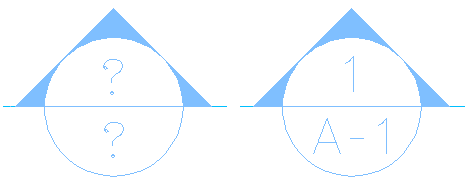
The predefined callout tools in AutoCAD Architecture 2025 toolset contain field placeholder information about the sheet number and the view number. This information can be resolved only when the model space view created by the callout is referenced into a sheet. As long as the model space view is not placed on a sheet, the information is unresolved, and a question mark is displayed.

Unresolved (left) and resolved (right) elevation callout symbols
Once the model space view is placed on a sheet, and the sheet information in the callout is resolved, a link is created between the field information in the model space view and the sheet on which it is placed. When you Ctrl-click the sheet number, the corresponding sheet drawing is opened.
- Create a model space view referenced to a callout.
- In the Project Navigator, click the Sheets tab, and click
 .
. - In the Sheet Set View, locate the sheet onto which you want to place the model space view.
- Open the sheet in one of these ways:
- Select the sheet, right-click, and click Open.
- Double-click the sheet.
The drawing containing the sheet is opened in the drawing area of AutoCAD Architecture 2025 toolset. The sheet you selected is the active layout.
- In the Project Navigator, click the Views tab.
- Select the model space view you want to place onto the sheet, and place it in one of these ways:
- Select the model space view, and drag it from the Project Navigator to the drawing area of the sheet.
- Select the model space view, right-click, and click Place on Sheet. Then, select an insertion point on the sheet.
When you open the model space view, you can see that the sheet information has been updated.