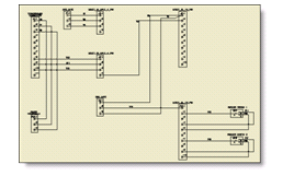
 Point-to-Point Style Schematic |
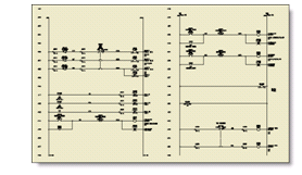
 Ladder Style Schematic |
In addition to the tools specifically related to connectors, you can utilize other tools in the AutoCAD Electrical toolset for editing your point-to-point wiring diagrams.
|
Edit Pin Numbers |
Use the Edit Component tool to edit the pin assignments on the parametrically generated connectors. |
|
Connector Dash Link Lines |
Use the Link Components (Dashed Line) tool to insert dash linked lines between parent and split-off child parametric connector symbols. |
|
Scoot Connector |
Use the Scoot tool to reposition the parametric connector along the same direction as the connected wiring. |
|
Scoot Wire |
Use the Scoot tool to move wires attached to pins on the connectors. The wire scoots and the connector pin along with it while the overall connector shell stays fixed. |
|
Insert Wires |
Use the Insert Wires tool to route single-wire connections. Use the Multiple Wire Bus tool, Component mode, to insert and route multiple wires in one tool. Note:
A wire connection point should only have up to three wire connections tied to it. Adding more wires to a single point prevents the angled wire connection to tie uniquely to the wire connection point. |