|
Tree View Graphically describes the hide situation. The name of the hide situation is the root node. Levels appear as child nodes of the root, listed in z-order. Names of blocks, component views, and folders in the hide situation appear in the tree under the respective levels. Elemental geometry such as lines and arcs selected for a level are shown as a single entity named free objects. |
||
|
Vertical Toolbar Contains buttons that operate on the item selected in the tree view. The availability of each button depends on its relevance to the selection. |
||
|
Buttons |
||
 Creates a level and adds it below the current selection in the tree. |
||
 Temporarily hides the dialog box so you can pick objects for the currently selected level.
|
||
 Removes the item selected in the tree. If the selected item is the root node, the entire hide situation is deleted, and 2 empty levels are created. If the hide situation contains only 2 levels, the levels are not removed, but all the contents within that level are removed. If the selected item is a level, that level and all its contents are removed from the hide situation. |
||
 Moves the selected level to the top. |
||
 Moves the selected level up one level. |
||
 Moves the selected level down one level. |
||
 Moves the selected level to the bottom. |
||
 Temporarily hides the dialog box to show the drawing. Press ESC or ENTER to return to the dialog box. |
||
|
Basic tab |
||
|
Level Settings |
||
|
Level Name Provides a space for you to specify a name for the level. The program shows this name on the tree view. |
||
|
Selection Shows the number of entities have been selected for that level. Occurrences refer to the number of mechanical structure objects that have been selected for that level. |
||
|
Auto Background Selection Sets automatic background selection options for the objects this level overlaps. This option is available only on a level that serves as a background |
||
|
Auto Select Automatically selects background objects and adds them to the selected level. |
||
|
Select Occurrences Only Restricts auto selection to component views and folders only. |
||
|
Advanced tab |
||
|
Level Settings |
||
|
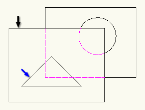
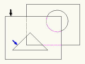
Use outer contour only Uses only the outer contour for foreground calculations. When selected, if there are openings such as holes and slots inside the contour, background objects are not visible through them. A common use for this option is hiding background objects when the foreground object contains blind holes. |
||
Examples: In this example, the foreground consists of the rectangle (black arrow) and a triangular opening (blue arrow) objects. Because Use outer contour only is selected, background objects are not visible through the opening. The program shows them using hidden lines.  In this example, Use outer contour only is not selected. The background objects are visible through the triangular opening. |
||
|
Save Contour Saves the outer contour of the foreground geometry for use with future hidden line calculations. When you modify the foreground, AutoCAD Mechanical toolset may not calculate hidden lines accurately, because the calculation is based on the saved contour and not the actual contour. Use this option only if you observe a significant degrading of performance when adding or modifying geometry. Note:
This option is available only if the Use outer contour only check box is selected. |
||
|
Inverse foreground Swaps the role of the foreground and background. The program hides objects that are not overlapped by the foreground boundary and shows objects that are overlapped by the foreground. |
||
|
Use only contour layers in foreground Applies a layer filter to the foreground selection set, filtering out all layers except the contour layers and non-mechanical layers. By default, AM_0, AM_1, and AM_2 are contour layers and you can define up to four contour layers. By default, the program draws all objects that are valid foreground objects on these layers. If you clear this check box, all objects that belong to the foreground selection set appear as foreground objects, regardless of whether they are valid foreground objects or not. |
||
|
Object Exclusion tab |
||
|
Objects used as Foreground |
||
 Temporarily hides the dialog box so you can select or remove objects from the foreground exclusion set.
|
||
 Clears current selection for the exclusion set. |
||
|
Exclude selected objects Specifies that the objects for the foreground exclusion set are not calculated as part of the foreground. |
||
|
Objects used as Background |
||
 Temporarily hides the dialog box so you can select or remove objects from the background exclusion set.
|
||
 Clears the current selection for the exclusion set. |
||
|
Exclude selected objects Specifies that the objects selected for the background exclusion set are not hidden as part of the background. |
||
|
Settings Opens the Hide Options dialog box and enables users to set defaults for AMSHIDE. |
||
- Set the defaults for this dialog box in the Hide Options dialog box (accessed through the OPTIONS/AMOPTIONS command AM:Structure tab
 Hide Options or Settings button on this dialog box).
 - You can resize the dialog box by dragging a side or corner.