The AMSHIDE command changes the line type (of overlapped objects) to indicate hidden edges, when you specify what objects lie on top of others.
Once you select the foreground objects, AMSHIDE automatically selects the background objects for you. However, if the number of background objects is too high, it prompts you to select the background objects manually.
Once you select the foreground objects, the Hide Situation dialog box appears and objects chosen for each level (foreground and background) appear in a tree. The program lists mechanical structure objects and blocks by name under the respective levels. It represents elemental geometry on the tree by a single node named Free Objects under the respective level.
Although by default a hide situation has only two levels (a foreground and a background), you can add more levels if necessary. Doing this enables you to handle complex hide situations that go beyond one that has only a foreground and a background.
You can drag-and-drop mechanical structure objects and blocks from one level to another. You cannot drag-and-drop elemental geometry because there are no individual entries for them (they group under a single node named Free Objects). To add objects to a level, select the level and use the  button.
If you are creating a hide situation for a mechanical structure-enabled drawing, pay attention to the tooltip when you select objects. The tooltip indicates whether you are selecting the elemental geometry or the structure component. In the non-structured environment, the tooltip does not matter. If you click an elemental geometry, it is selected as a free object. If you select a geometry that belongs to a block, the program selects the entire block.
AMSHIDE enables you to name a hide situation. When you save the hide situation, its name appears in the mechanical browser. To edit the hide situation, double-click the corresponding entry in the mechanical browser. By naming the hide situation appropriately you can easily differentiate between the different hide situations and quickly select them for editing.
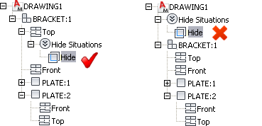
In a mechanical structure-enabled drawing, the position of the hide situation on the mechanical structure is important.

For example, if you create a hide situation between two parts of a subassembly, the most appropriate position to store the hide situation is on the subassembly. If you insert another instance of the subassembly in the drawing, the hide situation also inserts automatically because the hide situation is an integral part of the subassembly. Alternatively, if you store the hide situation directly under the drawing name (the root node of the browser) the hide situation does not show in any new instances you create because the subassembly does not store the hide situation.
The AMSHIDE command was originally designed as a mechanical structure command, thus the “AMS” prefix on the command name. However, since then we have enhanced the command to support non-mechanical structure workflows as well.