|
Revision Displays most recent revision of the standard this symbol complies with. |
|
|
Use ISO Standards Enables the use of ISO compliant welding symbols when JIS is the current standard. Accordingly, JIS welding symbols are allowed to have an identification line. It also makes ISO supplementary weld symbols available in the Symbols list. As such, you can make them available for use in the Weld Symbol dialog box. Note: This option is visible only for the JIS standard.
|
|
|
Identification Line Defines the appearance of identification lines. This section is not visible for ANSI, GOST, or JIS welding symbol. |
|
|
Linetype Defines the default linetype to use for identification lines. This option is available only for custom standards. |
|
|
Gap Sets the distance between the identification line (if added) and the reference line. 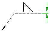
|
|
|
Symbol Filter |
|
|
Category Specifies what category of symbols to display in the Symbols list. |
|
|
Symbols list Displays a list of weld types and supplementary weld symbols supported by the current drafting standard. Select the check box in front of a weld symbol to make it available in the Weld Symbol dialog box. |
|
|
Symbol size |
|
|
Scale factor Specifies the magnification of weld type symbols, relative to the default size corresponding to the text height setting. The scale factor affects the following as well:
|
|
|
Process gap Specifies the gap between the first and second welding processes. This setting also controls the gap between a process and the contour symbol. 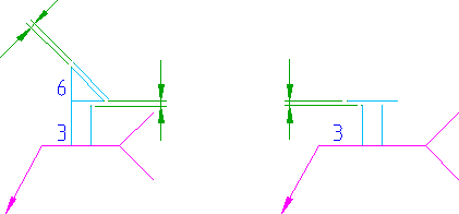 |
|
|
Leader |
|
|
Arrowhead Specifies the default arrowhead type for welding symbols. Note: If you select the arrowhead type labelled "By NameOfStandard", the arrowhead type is linked to the leader arrowhead setting of the master settings of the drafting standard. If the master setting change, the arrowhead type setting for welding symbols change accordingly.
|
|
|
Arrow size Specifies the default leader arrowhead size for welding symbols. Note: If you select the size labelled "By NameOfStandard", the arrow size is linked to the arrow setting of the master settings of the drafting standard. If the master setting change, the arrow size value for welding symbols change accordingly.
|
|
|
Color Specifies the default leader color for welding symbols. Note: If you select the color labelled "By NameOfStandard", the arrowhead color is linked to the leader color setting of the master settings of the drafting standard. If the master setting change, the color setting for welding symbols change accordingly.
|
|
|
Text |
|
|
Height Specifies the default text height for the symbol text of welding symbols. If the current standard is a "custom standard", you can specify a non-standard text height. If not, AutoCAD Mechanical toolset restricts you to selecting a value from the list. Note: If you select the text height labelled "By NameOfStandard", the text height is linked to the base height setting in the master settings of the drafting standard. If the master setting change, the text height setting for welding symbols change accordingly.
|
|
|
Color Specifies the default color for the symbol text of welding symbols. If the text height changes, the color automatically changes to the default color corresponding to that text height. Text object colors are set from the Object Property Settings dialog box. Note: If you select the color labelled "By NameOfStandard", the text color is linked to the text color setting in the master settings of the drafting standard. If the master setting change, the text color setting for welding symbols change accordingly.
|
|
|
Restore Defaults Returns all values to the default values for the drafting standard. |
|