Creates a welding symbol and attaches it to an object in the drawing area.
Find
Summary
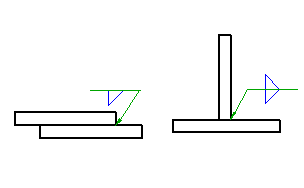
You can select graphical symbols for a wide range of welds. The Weld Symbol dialog box changes dynamically to show only the requirements corresponding to the weld type you select.
List of Prompts
The following prompts are displayed.
- Select object to attach
- Attaches the symbol to an object. To place the symbol without attaching it to anything, click the position you want to place the arrowhead of the leader. If you want to place the symbol without a leader, click the position you want to place the symbol.
- Start point
- Specifies the position of the leader arrow. If you attach the symbol to an arc, circle, ellipse or spline, AutoCAD Mechanical toolset automatically determines the start point and does not display this prompt.
- Next point
- Specifies the location of next vertex of the leader. Note:
- If you attach the symbol to an arc, circle, ellipse or spline AutoCAD Mechanical toolset forces the leader to be perpendicular to the attached object. To override this restriction, press the Toggle Symbol Leader Orthogonal Mode key (SHIFT + F, by default) as you move the cursor.
- If you attach the symbol to a line, AutoCAD Mechanical toolset does not enforce this restriction. To make the leader segment perpendicular to the attached line, move the cursor so that the leader is approximately perpendicular, and track along the alignment path that is displayed.
- Symbol
- Places the symbol at the most recently clicked location.
- Library
- Specifies that the symbol settings are obtained from the symbol library.
- Symbol name - Specifies the name of the pre-configured symbol to get from the symbol library.
- ? - Lists the names of the pre-configured symbols you can select.