Use the Surface Texture dialog box to specify the surface texture requirements for a surface.
- The elements in this dialog box depend on the current drafting standard and options you select. Some of the elements described in this page may not appear.
- Some buttons on this dialog box are only named in tooltips. Move the pointer over the buttons to see their names.
|
Symbol tab |
|||
|
Options Sets the options for the graphical display of the symbol. The availability of each option depends on the drafting standard and whether buttons are configured to appear or hide. The options are: |
|||
|
Symbol Type |
|||
|
Basic symbol Draws the basic symbol only. |
|||
|
Material removal required Inserts the “machining required” designation on the symbol. |
|||
|
Material removal prohibited Inserts the “machining prohibited” designation on the symbol. |
|||
|
Force tail Controls the availability of a tail for a symbol without text. |
|||
|
Add Adds a new reference line to the existing surface texture symbol. Note: This option is available only in the ANSI/ASME standard.
|
|||
|
Delete Removes the selected symbol from the surface texture symbol. This button is active only when 2 or more reference lines are added to the symbol. Note: This option is available only in the ANSI/ASME standard.
|
|||
|
Previous Moves from the current symbol to the previous symbol in a multi-reference line surface texture symbol. This button is active only when there are 2 or more reference lines, and the currently selected symbol is not the first symbol in the multi-reference line surface texture symbol.. Note: This option is available only in the ANSI/ASME standard.
|
|||
|
Next Moves from the current symbol to the next symbol in a multi-reference line surface texture symbol. This button is active only when there are two or more reference lines, and the currently selected symbol is not the last symbol in the multi-reference line surface texture symbol. Note: This option is available only in the ANSI/ASME standard.
|
|||
|
Use majority symbol Sets the symbol to be a collective indication of all other surface texture symbols in the drawing. This option is available only if you created the symbol without a leader. Note: Click Properties to select between the simplified and full-list representations. In the simplified representation, only the basic symbol appears in parentheses to the right of the collective indication. In the full list representation, the state of any surface texture symbol present elsewhere in the drawing is fully indicated in parentheses to the right of the collective indication. Full list is not an option for the GOST standard. Simplified is the default selection.
|
|||
|
Library Lists all the surface texture symbols for the active drafting standard/revision in the symbol library. When you move the pointer over an item, all settings for that item appear in a tooltip. Each item in the library is associated with a context-sensitive menu. |
|||
|
Menu options |
|||
|
Load Loads the selected symbol from the library. The current settings in the Surface Texture Symbol dialog box are overwritten. |
|||
|
Update Overwrites the selected symbol in the library with the current settings of the Surface Texture Symbol dialog box. The preview updates to reflect the new settings. The name of the symbol and default status do not change with this operation. |
|||
|
Delete Removes the selected symbol from the library. |
|||
|
Rename Makes the symbol name editable. The program validates the name you provide to ensure that the names of the symbols in the library are unique. |
|||
|
Set default Makes the selected symbol the default symbol of the library. A blue check mark appears next to the symbol to indicate that it is the default symbol. The next time you create a surface texture symbol, the default symbol loads automatically. |
|||
|
Remove default Removes the default status of the selected symbol. This menu option is available only on the default symbol. When no default symbol is selected, the surface texture symbol dialog box defaults to the settings of the surface texture symbol created or edited most recently. |
|||
|
Add Saves current settings to the symbol library as a new item in the library. A prompt enables you to name the new item. |
|||
|
Import Imports the surface texture symbols from the symbol library of another drawing. You can only import symbols of the same standard and revision as the surface texture symbol you are editing. |
|||
|
Requirements Sets the options used to specify surface texture requirements. The boxes used for data entry appear as and when you add data. The order in which the boxes appear depends on the type of weld you select and therefore may be different to the order in which they appear in the following list. When you move the pointer over a box, the tooltip describes what information to enter to that box. |
|||
|
Insert symbol Displays a palette to enable you to insert a special character at the current cursor position. The preview in the drawing area shows the special character while the dialog box shows the corresponding control key sequence. |
|||
|
All around Inserts the all around indication to the symbol. |
|||
|
All over Inserts the all over indication to the symbol. |
|||
|
Machine allowance Specifies the machining allowance for the surface. Not available in the GOST standard. |
|||
|
Roughness average max Specifies the maximum roughness average for the surface. |
|||
|
Roughness average min Specifies the minimum roughness average for the surface. |
|||
|
First requirement Specifies the first requirement for the surface. |
|||
|
Second requirement Specifies the second requirement for the surface. |
|||
|
Third requirement Specifies the third requirement for the surface. |
|||
|
Fourth requirement Specifies the fourth requirement for the surface. Note: This option is available only in the GOST standard.
|
|||
|
Texture Direction Identifies the direction that the texture should take. Note: This option is available only in the GOST standard.
|
|||
|
Production method Specifies the production requirement for the surface. User added values that are not identical to existing values are added to the drop-down list. Note: This option is available only in the GOST standard.
|
|||
|
Processing note Specifies the process requirements for the surface. |
|||
|
Process note 1 Specifies the process requirements for the surface. |
|||
|
Process note 2 Specifies the process requirements for the surface. |
|||
|
Sampling length Specifies the sampling length required for the surface. |
|||
|
Maximum spacing Specifies the maximum spacing for the surface. |
|||
|
Cutoff Specifies the cutoff value for the surface. |
|||
|
Reference Specifies the reference and evaluation length for the surface. |
|||
|
Waviness Specifies the waviness value for the surface. |
|||
|
Other roughness Specifies the other roughness for the surface. |
|||
|
Other roughness max Specifies the maximum other roughness for the surface. |
|||
|
Other roughness min Specifies the minimum other roughness for the surface. |
|||
|
Direction of lay Specifies the direction of lay for the surface. |
|||
|
Base length Enables force tail option when a value is present. This option is available only for the 1973 GOST standard. |
|||
|
Profile Parameter Specifies the requirement for the surface profile parameter. |
|||
|
Profile filter 1 Specifies the requirement for the surface profile filter 1. |
|||
|
Profile filter 2 Specifies the requirement for the surface profile filter 2. |
|||
|
Evaluation length Specifies the requirement for the evaluation length. |
|||
|
Profile operator Specifies the requirement for the surface profile operator. |
|||
|
Profile extraction method Specifies the requirement for the surface profile extraction method. |
|||
|
Manufacturing process Specifies the process requirement for the surface. |
|||
|
Identical elements Specifies the number for identical feature elements. |
|||
|
Profile direction Specifies the profile direction requirement to surface of lay. |
|||
|
Transmission band Specifies the cutoff values for short and long wavelengths, and the associated filter types. |
|||
|
Roughness parameter Specifies the surface texture parameter designation and limit values. |
|||
|
Calculation type Specifies the calcution type for the surface texture. |
|||
|
Clear Clears all the data and returns the dialog box options to the default values. |
|||
|
Add Row Adds a new row in the existing surface texture symbol. |
|||
|
Delete Row Removes the selected row of the surface texture symbol. This button is active only when 2 or more rows exist in the symbol. |
|||
|
Previous Row Moves from the current row to the previous row. This button is active only when there are 2 or more rows, and the currently selected row is not the first row in the surface texture symbol. |
|||
|
Next Row Moves from the current row to the next row. This button is active only when there are two or more rows, and the currently selected row is not the last row in the surface texture symbol. |
|||
|
Leader and Text tab |
|||
|
Arrowhead Specifies the type of the leader arrowhead. When the arrowhead is set to By Standard, it acquires the arrowhead from the current drafting standard. Thereafter, if you change the arrowhead selected for the current drafting standard (in the Standard Settings dialog box.or Surface Texture Settings dialog box.) the arrowhead for this symbol updates automatically. Note: When the leader attached to the symbol is a surface indication leader, the name of this option changes to Surface arrowhead.
|
|||
|
Edit leader segments |
|||
|
Add Adds a leader, leader segment, or leader node. |
|||
|
Remove Deletes a leader, or leader segment. |
|||
|
Edit object attachment |
|||
|
Attach Attaches the symbol to an object in the drawing. When attached, if you move the object the symbol moves with it. |
|||
|
Detach Detaches the symbol. The symbol becomes a free-standing object. |
|||
|
Lineweight scale Enlarges or reduces the size of the graphical symbol. The drawing area shows a dynamic preview of the symbol while you change the scale factor. During scaling, the system maintains the line weight at 10% of the symbol text height. When you enlarge or reduce the size of the symbol, the scale factor snaps only to a value for which a valid line weight is available.Note: This option is available only if the symbol is not attached to an object.
|
|||
|
Surface extension line Controls options for extension lines to the start point of the leader. Extension lines are drawn only if you move the start point of the leader beyond the end of the line or arc it is attached to. The options in this section are available only if extension lines for this symbol exist. |
|||
|
Offset from object Defines the distance between the extension line’s start point and the attached object. |
|||
|
Sync Loads values for the offset from the DIMEXO system variable. 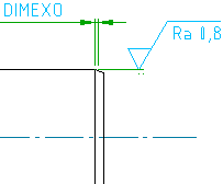
|
|||
|
Extension beyond leader Defines the distance between the symbol’s start point and the surface extension line’s end point |
|||
|
Sync Loads values for the extension from the DIMEXE system variable. 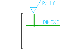
|
|||
|
Automatically adjust symbol position on leader Select this option to move the symbol to the default position on the leader. |
|||
| Text | |||
|
Automatically adjust symbol position on leader Moves the symbol to the default position on the leader. |
|||
|
Settings Opens the Surface Texture Settings dialog box and enables you to edit the default settings for surface texture symbols for the current drafting standard. |
|||