You can set up selected dimensional constrains to obtain their values by a drag operation.
When you insert the content in a drawing, you are prompted to “drag size”. It also displays the name of the dimensional constraint in a tooltip. If dimensional input is enabled, you can enter the dimension value in the corresponding tooltip.
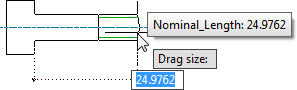
Because the name of the dimension is displayed in a tooltip, it is important to name dimensional constraints meaningfully.
You can configure more than one dimension to obtain values by dragging. In such a case, AutoCAD Mechanical toolset prompts you for each drag operation sequentially. The tooltip provides information on the dimension you are dragging.
In the Content Editor, you specify which dimensional constraints require drag and the drag sequence.
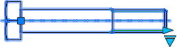
If you select a part/feature after it is inserted in a drawing, AutoCAD Mechanical toolset displays drag grips for dimensions set up for dragging. In the Content Editor, you specify if the drag grip appears on the first extension line or the second. The preview in the Content Editor updates to show the drag grip. If the part/feature is a symmetrical object, you can add drag grips to both extension lines.
You cannot make the following dimensional constraints draggable:
- Dimensional constraints that have been made key columns in the Family Table.
- Dimensional constraints that derive their values from a user variable or another dimension.
- Dimensional Constraints that have fixed values.
In the Parameters Manager, only the dimensional constraints that have their “size selection” property as “drawtime” can be selected for dragging.
When the Family Table controls a draggable dimension, the size snaps to valid values (as defined in the Family table) as you drag. All other dimensions controlled by the Family Table are set to corresponding values.
You can also set the minimum and maximum values for a draggable dimension. Using this feature you can restrict dragging to a defined limit. For example the thread length of a screw.