When you double click a symbol in the drawing area, the feature control frame dialog box displays.
Edit Symbol Data
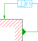
You can edit the tolerance data as well as introduce the all around designation or remove it.
Edit Leaders
When you double click the symbol leader, the leader tab displays. You use the buttons on this tab to add or remove leaders and leader segments.
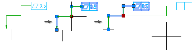
When you add a leader and terminate it on the feature control frame, the leader automatically becomes a secondary leader. AutoCAD Mechanical toolset allows only one secondary leader per symbol.
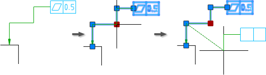
When you add a leader and terminate it on an existing leader, AutoCAD Mechanical toolset converts the symbol to one that has multiple leaders. The original leader splits into two separate segments at the junction point.
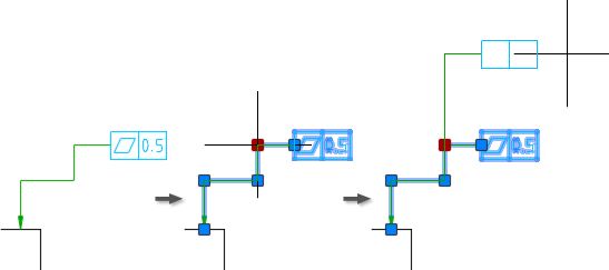
When you attempt to add a leader, AutoCAD Mechanical toolset provides a command line option that is named Auto route. When you select this option you do not have to select the termination point. If there is no secondary leader, it adds the leader as a secondary leader. If a secondary leader exists, it adds the leader as an additional leader.
If you pick a leader segment for removal, all leader segments after that leader segment are deleted as well.
Grip Edit Leaders
When you select a leader, AutoCAD Mechanical toolset displays grips on the leader. You can drag the grips to stretch or contract leader segments. When you grip edit a leader, the drag operation obeys the rules under which the leader was created. For example, if the first leader segment is perpendicular to the attached object, during grip edit,AutoCAD Mechanical toolset forces it to remain perpendicular. If a subsequent leader segments is either horizontal or vertical, during grip edit,AutoCAD Mechanical toolset forces them to be horizontal or vertical.
However, if you press the Toggle Symbol Leader Orthogonal Mode key (SHIFT + F, by default) while grip editing such leader segments, AutoCAD Mechanical toolset relaxes the rule.
Similarly, if a leader segment was originally created with the rule relaxed, the rule remains relaxed when you grip edit that leader segment. However, if you press the Toggle Symbol Leader Orthogonal Mode key (SHIFT + F, by default) while grip editing such leader segments, AutoCAD Mechanical toolset enforces the rule.
When you grip edit a primary leader, the leader segment before the Grip Point (towards the arrowhead) stretches or contracts. None of the other leaders are affected. The position of the feature control frame changes accordingly.
If the symbol has a secondary leader, the first leader segment (of the secondary leader) stretches or contracts to absorb the change in the position of the symbol.
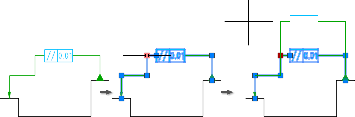
When this behavior is not able to accommodate the change, the start point of the first leader segment changes.
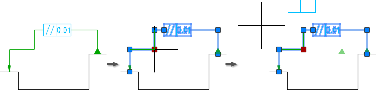
When a symbol has multiple leaders, and you drag the junction point, all leader segments before the grip point stretch.
When you grip edit the secondary leader, the leader segment before the Grip Point stretches, but the symbol does not move. Hence, you can only grip edit secondary leaders only within the available space.