The feature control frame is a rectangular frame that is divided into two or more sections.
Symbol Anatomy
The sections contain the symbol for the characteristics to be toleranced, the tolerance value, and, if appropriate, the letter or letters identifying the datum relative to which the tolerance is specified. The tolerance frame connects to the toleranced feature by a leader line terminating with an arrow.
A geometrical tolerance applied to a feature defines the tolerance zone within which the feature is to be contained. You can supplement feature control frame symbols with notes. If necessary, you can specify more than one tolerance characteristics for a feature, the tolerance specifications appear in tolerance frames one under the other.
The appearance of the symbol depends on the current drafting standard and revision that you selected.
Orthogonal Leaders
When you attach a feature control frame to an object, AutoCAD Mechanical toolset forces the first leader segment to be perpendicular to the attached object. Subsequent leader segments are forced to be either horizontal or vertical. If you want to override this behavior, press the Toggle Symbol Leader Orthogonal Mode key (SHIFT + F, by default) as you move the crosshairs.
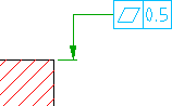
Surface Extension Lines
 |
 |
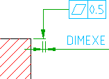
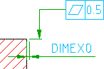
If you move the start point of the leader beyond the end of a line or arc AutoCAD Mechanical toolset automatically draws extension lines. The default values for overshoot length and offset from end of leader is determined by the DIMEXE and DIMEXO system variables, respectively. AutoCAD Mechanical toolset does not create extension lines for splines.
 |
 |
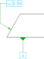
Secondary Leaders that Identify Datums
You can draw symbols that use a secondary leader to identify the datum, relative to which the tolerance is specified. However, to create such a symbol you must first create it as a symbol with a single leader. Thereafter you edit the symbol and add the secondary leader. When you select the Auto route command line option, while adding the secondary leader, you only have to select the attach points. The leader will automatically draw a leader where the first segment is perpendicular to the attached object and all subsequent leaders are either horizontal or vertical.
Not all standards allow secondary leaders to identify datums. Refer the table in the section Summary of supported drafting standards for details.
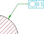
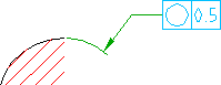
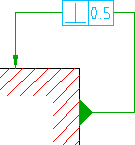
Surface Indication Leaders
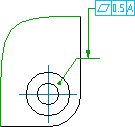
AutoCAD Mechanical toolset provides command line options to create surface indication leader. This enables symbol leaders to point to a surface rather than an edge. Using surface indication leaders you can indicate requirements using a top view rather than a side view.
Attach to Dimensions
AutoCAD Mechanical toolset provides options to attach and align symbols to dimensions as shown below.
| Example | Description |
|---|---|
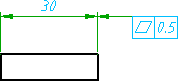 |
Attach to a linear dimension and align to dimension line (when dimension arrows are inside extension lines) |
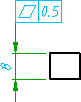 |
Attach to a linear dimension and align to dimension line (when dimension arrows are outside extension lines) |
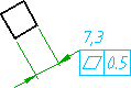 |
Attach to horizontal landing of a dimension (Supported only by the GOST standard) |
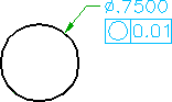
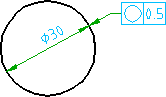 |
Align to a diameter dimension |
 |
Attach to dimension text of diameter dimension |
Supported Drafting Standards
| Standard/Revision | Orthogonal Leaders | Surface Extension Lines | Datum Identification Leaders | Surface Indication Leaders |
|---|---|---|---|---|
| ANSI ASME Y14.5 M -1994 | Yes | Yes | Yes | |
| ASME Y14.5M - 1982 | Yes | Yes | Yes | |
| BSI EN ISO 1101:2013 | Yes | Yes | Yes | |
| BS 308 Part 3 -1990 | Yes | Yes | Yes | |
| CSN EN ISO 1101:2013 | ||||
| CSN 01 3138 -1994 | Yes | Yes | Yes | |
| DIN ISO 1101:2008 DIN EN ISO 5459:2008 | Yes | Yes | Yes | |
| DIN ISO 1101:1983 DIN EN ISO 5459:1982 | Yes | Yes | Yes | |
| GB/T 1182 -2008 | Yes | Yes | Yes | |
| GB/T 1182 -1996 | Yes | Yes | Yes | |
| GOST 2.308-79 | Yes | Yes | Yes | |
| ISO 1101:2012(E) | Yes | Yes | Yes | |
| ISO 1101:2004 | Yes | Yes | Yes | |
| ISO 1101:1983 | Yes | Yes | Yes | |
| JIS B 0021 (1998) | Yes | Yes | Yes | |
| JIS B 0021:1984 JIS B 0022:1984 | Yes | Yes | Yes |