Recommendations and Considerations for User Input
View recommendations for inputs with woven materials.
While the discussion in the previous section may seem an oversimplified approach, the limitations of experimental data force the simplification of the geometry. Typically, you will only know the total fiber volume fraction, and some information regarding whether the weave is balanced or unbalanced. In an attempt to keep all information consistent, Composite Material Manager requires you to input the total fiber volume fraction of the composite and the bundle volume fractions of the tows to define the unit cell.
The link between the spacing of the tows and their respective bundle volume fractions is complex and has been developed by Kuhn and Charalambides [1] in their discussion of the unit cell. While the discussion presented in this work does not cover this material, we do need to present some recommendations and some fundamental relationships that may be used to give a good description of your woven geometry.
For any woven composite material being characterized by Composite Material Manager, the tow fiber volume fraction is automatically computed using Eq. 3 as
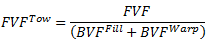 , (Eq. 4)
Typical woven composite materials have tow fiber volume fractions between 0.65 and 0.85. When using the recommendations presented in this section, you are encouraged to check the computed tow fiber volume fraction to ensure the value falls in the acceptable range. Furthermore, it is highly recommended that you check all material properties output by Composite Material Manager. If the output constituent and composite material properties are not acceptable, bundle volume fractions should be slightly modified until acceptable material properties have been acquired.
Balanced Plain Weaves
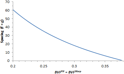
To begin the discussion on recommended parameters, let us first consider the case of a balanced plain weave. This case can be described using a two-dimensional space because the bundle volume fractions and spacing are equal. The plot below shows the relationship between the bundle spacing and the resultant bundle volume fractions for a unit cell of equal width and height (34.04 units). Note that exact units are not important to this discussion, as they are divided out when computing bundle volume fractions. Due to limitations of the meshing algorithm and geometry of the unit cell, the acceptable values of the volume fraction for a balanced plain weave must be between 0.2 and 0.377. If you do not know the exact values of the bundle volume fractions for a balanced plain weave, it is recommended you use a value of 0.375 for both the fill and warp bundle volume fractions.
Unbalanced Plain Weaves
Unbalanced plain weaves are inherently more difficult to describe, as the geometry is a function of two different bundle volume fractions. For the remainder of this discussion, we assume the direction with the stiffest composite response is oriented along the fill direction, and thus the 11-direction. If the direction of stiffest response is oriented with the warp tows, the following relations may easily be switched.
For unbalanced plain weaves, the meshing algorithm and the geometry of the unit cell require that the sum of the fill and warp volume fractions generally satisfy
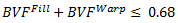 , (Eq. 5)
and
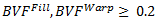 , (Eq. 6)
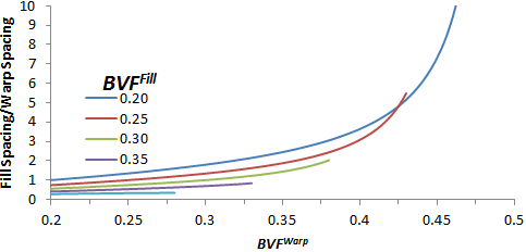
Note that this is inherently a three-dimensional space consisting of the fill volume fraction and the warp volume fraction as a function of the fill gap spacing and the warp gap spacing. To simplify this space and give you a feel for the range of volume fractions associated with the range of spacing, consider the graph below. It shows the ratio of fill spacing to warp spacing as a function of the acceptable range of warp volume fractions for several fill volume fractions. Note that these relationships are easily switched to accommodate a constant warp volume fraction and a range of fill volume fractions. Using the graph below, you can estimate acceptable fill and warp volume fractions knowing the fill spacing and warp spacing ratio. As a general starting point, Autodesk recommends using 0.375 for the bundle volume fraction of the tow orientated with the stiffest material response of the composite.
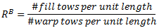
If you do not have access to the fill and warp spacing for the selected unbalanced weave, Autodesk has developed reference parameters which generally provide acceptable results. The first of these parameters is the ratio of the linear density of warp tows to fill tows
Knowing this parameter, and assuming the fill bundle volume fraction to be 0.375, the table below can be used to compute the necessary warp bundle volume fraction of the woven composite.
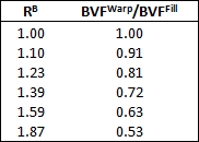
The results presented above provide exact relations for the bundle volume fractions as a function of tow ratio, RB, with the assumptions made in developing the micromechanics model used by Composite Material Manager. While the above discussion provides accurate starting points for developing an unbalanced woven material characterization using Composite Material Manager, it is still possible you cannot acquire the information necessary to generate the geometry of the unit cell.
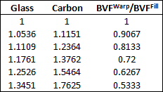
If you do not have access to the bundle spacing or the tow ratio, Autodesk has developed some recommended guidelines for determining the bundle volume fractions of the composite using the in-plane stiffnesses of the composite. Knowing the ratio of the in-plane stiffnesses of the composite and the type of reinforcement used (glass or carbon), the table below can be used to develop initial estimates for the bundle volume fractions of the fill and warp. We note that utilizing the bundle volume fractions found in this table does not guarantee the stiffness ratio will correspond exactly to the listed values. Depending on the constituent properties you supply, these values can vary slightly.
Satin Weaves
The unit cell developed for use within Composite Material Manager can take the form of a plain weave, 4, 5, or 8-harness woven composite microstructure with orthogonal tows. The entire discussion thus far has been centered on developing recommendations for user input of bundle volume fractions of balanced and unbalanced plain weaves. The satin weave microstructures have limits on the bundle volume fraction that vary from those provided earlier for plain weaves.
Full Unit Cell
- 4-Harness - 0.24 ≤ BVF ≤ 0.40
- 5-Harness - 0.28 ≤ BVF ≤ 0.42
- 8-Harness - 0.25 ≤ BVF ≤ 0.41
Reduced Unit Cell
- 4-Harness - 0.24 ≤ BVF ≤ 0.4
- 5-Harness - 0.28 ≤ BVF ≤ 0.4
- 8-Harness - 0.25 ≤ BVF ≤ 0.4
If you do not know the exact values of the bundle volume fractions for your satin weave, we recommend you use a value of 0.375 for both the fill and warp bundle volume fractions.
Twill Weaves
Even though the micromechanics model has been limited to plain woven composite materials and a select variety of satin fabrics, the plain weave can still be employed to generate a set of material data for twill weaves. However, for other variations of satin or twill weaves, the upper bounds of the structural response of the model should be computed by utilizing a cross-ply laminate.
References
- Kuhn, J. L. and P.G. Charalambides, 1999, "Modeling of Plain Weave Fabric Composite Geometry," Journal of Composite Materials, Vo. 33, pp. 188-220.