Woven Microstructure Development
Review details of the geometry, microstructure, and limitations for woven materials.
Geometry Generation
Currently, Composite Material Manager supports five types of microstructures. The first and simplest, is the unidirectional composite consisting of fibers embedded in a matrix material. The remaining four consist of the two-dimensional woven microstructures. This includes plain woven, 4-harness, 5-harness, and 8-harness composites.
For any microstructure, geometric parameters are necessary to construct a realistic model. In the case of a unidirectional material, only the fiber volume fraction (FVF) of the unidirectional composite material is required. Using the FVF and assuming a hexagonal fiber packing arrangement, the geometry of a micromechanics model is developed for the desired composite. However, woven fabric geometry is much more complex for two reasons:
- Many parameters are necessary to describe the geometry of the unit cell
- No universal set of data is used to describe the geometry of a plain weave.
Two dimensional woven materials come in a variety of combinations such as balanced plain, unbalanced plain, twill, and satin weaves, to name a few. The current models used within Helius PFA include two-dimensional plain woven, and 4, 5, and 8-harness woven microstructures. For other woven configurations that contain only orthogonal tows, such as twills, the plain weave model provides a reasonable estimate, however it is left to you to determine the accuracy of results. Thus, it is recommended that you calculate an upper bound for the lamina material properties by modeling the material as a cross-ply unidirectional laminate (where each ply represents a distinct tow direction). For microstructures with non-orthogonal tows, such as triaxial braids, Autodesk does not currently provide modeling capabilities.
The next sections describe the woven fabric microstructure implemented with Helius PFA and will give insight into choosing the necessary parameters to correctly characterize your woven material.
Plain Weave Microstructure
The plain woven composite micromechanics model consists of fill tows, warp tows, and a matrix pocket. The fill and warp tows are assumed to be perpendicular to each other. The unit cell chosen to model this type of microstructure was taken from Kuhn and Charalambides [1], and is shown below.
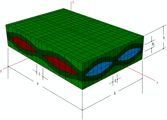
As seen above, there are many parameters required to completely describe the geometry of the unit cell. These include:
- The length of the unit cell
- The width of the unit cell
- The height of the total unit cell
- The height of the fill tows
- The height of the warp tows
- The spacing between the fill tows
- The spacing between the warp tows
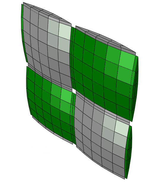
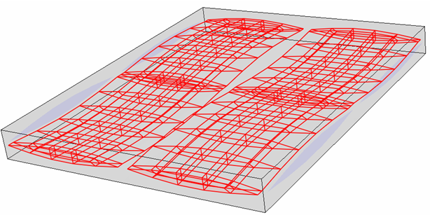
A view of the unit cell without the matrix pocket is shown below.
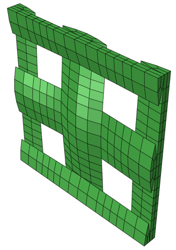
Reduced Unit Cell Microstructure (Satin Weaves)
The Reduced Unit Cell (RUC) microstructure for satin weave materials is an adaptation of the Full Unit Cell microstructure. The RUC is simply a subset of the repeating geometry found in the FUC. Rather than adjusting the microstructure for each n-harness material, the RUC maintains a constant size and topology. Only the amplitude of the curvature of the two center tows are adjusted as the harness number changes.
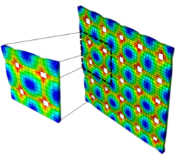
Specifically, the amplitude is adjusted to allow the average in-plane stiffnesses (E11, E22, G12) to match experimentally observed values for each harness number.
The RUC microstructure has the distinct advantage that it is smaller than the FUC and therefore, much faster to characterize. As a result, the RUC microstructure supports on-the-fly degradation of fiber and matrix stiffnesses. It also supports pre-failure nonlinearity, which is not supported for the FUC.
Experimental Data Limitations
Experimental data for fiber reinforced woven composite materials typically only characterize the fiber volume fraction for the entire composite. Like fiber reinforced unidirectional composite materials, this gives a measure of the total volume that the fibers occupy within the composite relative to the total volume of the composite. While this works well for unidirectional materials, this does not capture the geometry of the woven microstructure. One fundamental question must be answered to link the geometry of the unit cell to the parameters described above. What are the volume fractions of the fill and warp tows?
To answer this question, we must first develop the relationships between volume fractions. Total fiber volume fraction of the composite material can be described in terms of the volume fractions of the fill and warp tows, as well as their respective fiber volume fractions as
FVF = BVFFill (FVFFill ) + BVFWarp (FVFWarp ) , (Eq. 1)
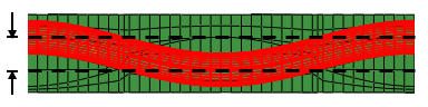
where BVFFill is the fill bundle volume fraction, BVFWarp is the warp bundle volume fraction, FVFFill is the fiber volume fraction of the fill tow, and FVFWarp is the fiber volume fraction of the warp tow. A bundle volume fraction is defined as the fraction of the volume the specified tow occupies compared to the entire composite. To present a more detailed discussion on bundle volume fractions and their meaning in the context of the geometry of the plain weave unit cell, consider the image below. The red highlighted region represents the volume the fill tows occupy in the entire composite unit cell. The fill bundle volume fraction is calculated as the volume of the fill tows divided by the volume of the composite.
Assumptions
Here we make a few assumptions about the geometry of the unit cell. First, we assume the fill and warp tow heights are equal, eliminating the dependency on both heights. The second assumption defines the total height of the unit cell and the height of the tows to be constant for any geometry specification. This effectively eliminates the third, fourth, and fifth dependency in the list above.
Finally, we assume the widths of the tows are equal and constant. Therefore, the width and length of the unit cell may be related to the spacing of the tows as:
a = width + 2f
b = width + 2g , (Eq. 2)
Therefore, only two unknown parameters are needed to completely describe the geometry of the unit cell; the spacing between the fill tows and the spacing between the warp tows. These parameters are directly related to the volume fractions of the fill and warp bundles, and to the number of undulations per unit length. Composite Material Manager uses bundle volume fractions (BVFs) to define the microstructure.
We assume the fiber volume fractions of the fill and warp bundles are equal, thus reducing Eq. 1 to
FVF = (BVFFill + BVFWarp )FVFTow , (Eq. 3)