To Work with Flanges in Sheet Metal
A flange can be along an edge or loop, or identical to an existing face.

If the faces merge, try using an offset plane to define the flange.

Create Flange along Edge or Edge Loop
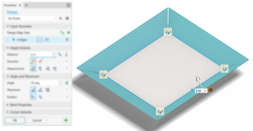
You can add a sheet metal face and bend connected to an existing sheet metal face with a specified angle. When you create the flange, the flange previews along the edge you select using default parameters, the last used values, or a preset.
If you don't want to see the transitional reference plane during the flange creation process, you can change the display preference. Click the property panel Advanced Settings menu (top right) and select Hide reference plane.

Hover the cursor over any input field to see the parameter and its value.
On the ribbon, click Sheet Metal tab
 Create panel
  Flange
  .
.(Optional) Use a preset that you have created from a previous flange feature.
Input Geometry group in Flange Edge Sets, do one of the following:
Edge Select Mode is active by default, select one or more edges on which to create flanges.
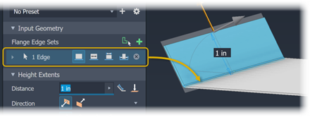
To create multiple flanges around an edge loop, click
 Edge Loop Select Mode, and then select a loop.
Edge Sets consist of one or more edges. Each edge set in the feature has per edge parameters and feature parameters (these are height, angle, and width). For Loop edge sets, all edges use the same edge parameters.
Expand a set and the edges comprising the set to access their parameters.
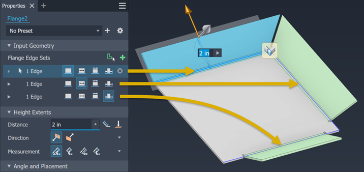
Select the edge option to use, choose from
 Edge,
Edge,  Width,
  Between, and
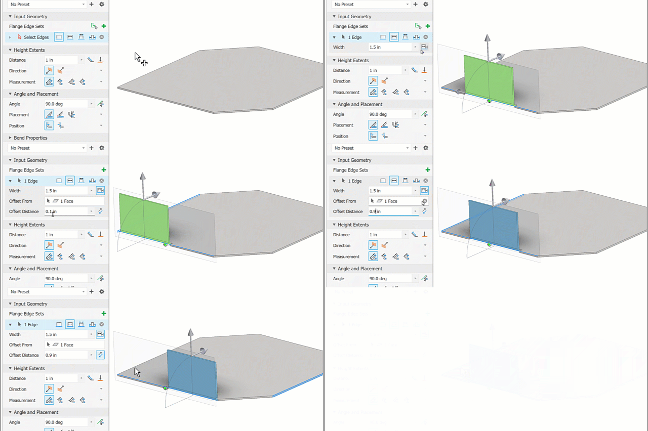
  Offset. Then, expand the edge row to expose the parameters for modification.
 Note: As you change the flange edge option, additional input controls for the type are exposed allowing for greater control of the flange output.
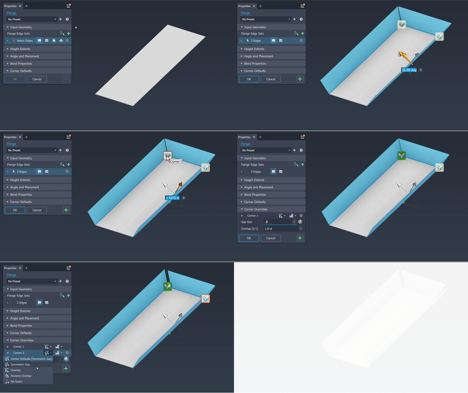
Use the feature manipulators to implicitly adjust the flange angle and height. Clicking a manipulator displays a canvas input field that you can use to explicitly specify a value or you can specify the values in the property panel.
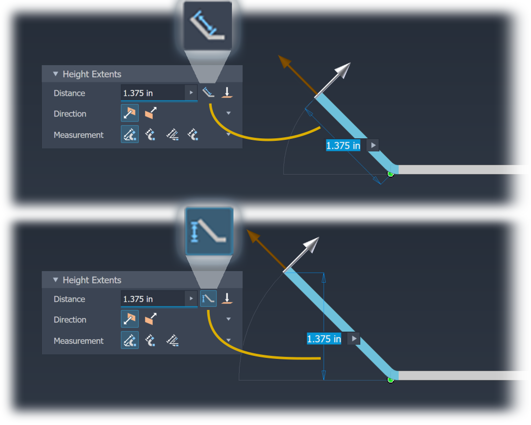
In the Height Extents group, you can do the following:
Click in the Distance field and enter a value.
Select Aligned (default) or Orthogonal to have the distance apply to the edge direction.
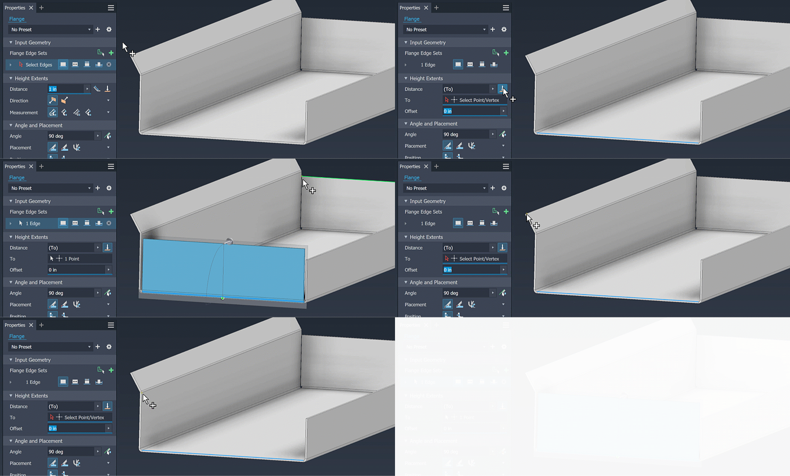
Select To and specify a vertex (point) that defines the flange height.
For Direction, select the side of the sheet metal face that the flange is on.
For Measurement, select the measurement method, choose from the intersection of the
 two outer faces, the intersection of the
  two inner faces, from a
  selected edge, or from a
  tangent plane.
In the Angle and Placement group, specify the following:
Enter the angle value. The field accepts numeric entries, formulas, parameters, or measured values.
Set the Flange Angle option to By Reference and select a face to create a coplanar flange. The adjacent flange length adjusts to enable the coplanar condition.

If you do not want the outside face of the bend to align to the selected edge, specify the bend position relative to the selected edge.
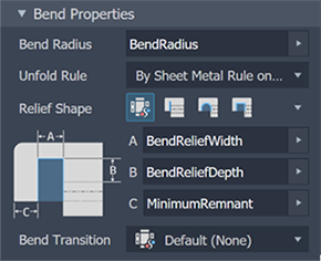
In the Bend Properties group, you specify the Bend Radius, Unfold Rule, Relief Shape, and Bend Transition you want to use. You can modify some parameters with explicit values or equations, or accept the default settings.
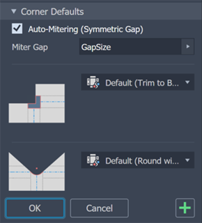
In the Corner Defaults group, you set the Auto-mitering option, the Corner Shape, and Corner Relief. Select corner options from the corresponding list.
In the canvas, for multi-edge flanges, you can specify individual corner parameters by means of Corner Overrides. Click a corner glyph to populate the corner in the property panel. Then, modify the corner settings for relief, shape, gap size, and relief size to fit your requirements.
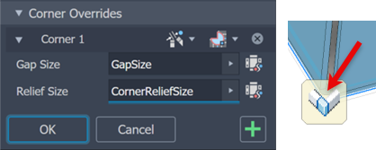
To enable gap and relief size fields, click the
 defaults icon next to the field.
To add more flanges, click Apply. If you are finished click OK.
Create Flange aligned with a Face or Plane
You can add a sheet metal face and bend connected to an existing sheet metal face with an angle that matches your selection. When you create the flange, the flange previews along the edge you select using default parameters.
The original face is extended or trimmed to attach the flange to the reference plane.
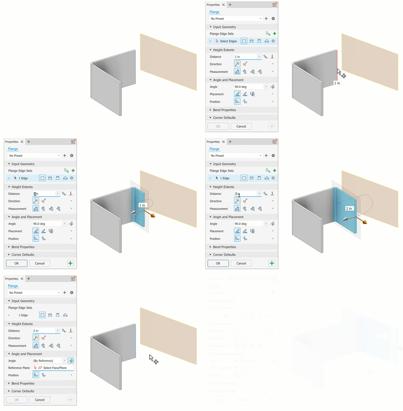
On the ribbon, click Sheet Metal tab
 Create panel
  Flange
  .
.Edge Select Mode is active by default, select an edge.
In the Height Extents drop-down list, do one of the following:
- For Distance and enter a value in the drop-down list below it.
- Select To and specify a geometry that defines the flange height.
- Modify Direction and Measurement settings to meet your requirements.
- To change the side of the sheet metal face that the flange is on, click Flipped.
In Angle and Placement, for Angle, specify the following:
- Set the Flange Angle option to By Reference
 to match the angle of the selected planar face, planar surface, origin plane, or work plane.
 - Select the reference face or plane.
- Set the Bend Position to Inside of Reference Plane, or Outside of Reference plane.
- Specify the Bend Radius or accept the default BendRadius parameter.
- If not the intersection of the two outer faces, specify the datum from which to measure the height.
- Set the Flange Angle option to By Reference
To continue adding flanges, click Apply. To end flange creation, click OK.
Create Symmetrical Flanges Using Mirror
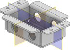
One method of creating identical symmetrical flanges is by using the Mirror command.
Start by creating a Face symmetrical about the Origin planes or work planes.

Create the flanges and other features to mirror.

Start the Mirror command. Select all the features that you want to mirror, select the mirror plane, and then click OK to finish.
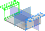
Create the next set of flanges and other features to mirror.
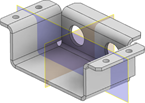
Start the Mirror command. Select all the features that you want to mirror, select the mirror plane, and then click OK to finish.
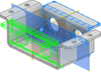
Turn off the visibility of the mirror planes when you finish.
