About Flanges in Sheet Metal
A flange feature consists of a face and bend connected to an existing face along a straight edge.
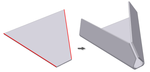
To add a flange feature, you select one or more edges, and specify the size and position of the material added.
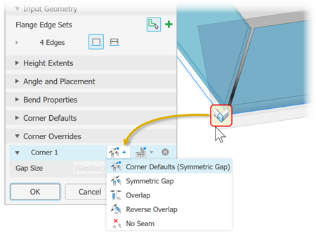
Corners that generate during the creation of flange and contour flange features display the default corner relief shape when the model is flat. You can override the default sheet metal style settings using the Unfold Options, and the Bend or Corner tabs. While selecting edges for a multi-edge flange, edit glyphs appear along bends and where the created flanges share corners. In certain cases, the auto-mitering option can automatically trim material that interferes along the end of each flange when you create a multi-edge flange.
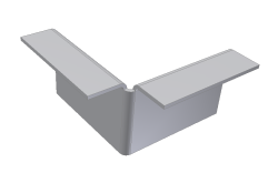
Not all corners provide the glyph edit option. For example, in the following illustration there is no edit glyph when a flange is on the top edges and the outside radius of the added flange is on the opposite side of the outside radius of the bend between the two selected edges.
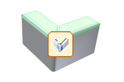
However, if you create the flange in the opposite direction, as in the following illustration, the three bends converge and their outside radii of the flanges are on the same side as the outside radius of the bend between the selected edges. This condition provides an edit glyph during creation or subsequent edit.
Flanges and Multiple Edges
Flanges that share a common corner automatically show a full or partial miter.
Flange miters are created when the selected edges are both coplanar and nonparallel.
If the flange extents are close enough (depending upon the miter-gap), a full corner is created.
If the flanges intersect, a partial miter is created.
If the edges meet at common bend so that all three bends face inwards, a three-corner bend is created.
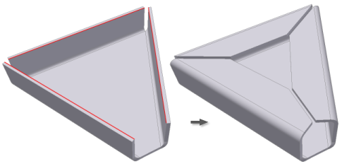
Flanges that are not coplanar also auto-miter.
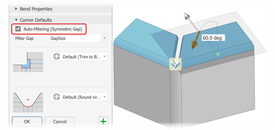
If adjacent flanges do not preview with miter corners, verify that Auto-Mitering is selected on the Flange property panel, in the Corner Defaults section.
Clicking on the corner glyph displays the Corner Override group in the property panel. Click the Use Defaults button to toggle on or off the use of corner default settings.
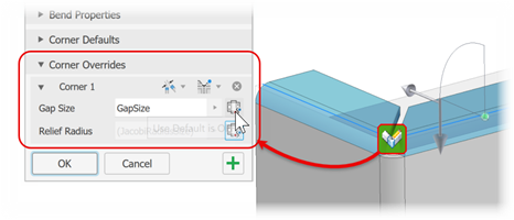
Click the Gap or Corner Defaults buttons to access the various options
