Create a Simplified Part from an Assembly
The Simplify command creates either a derived solid or a derived surface composite part from an assembly.
What's New: 2022, 2023, 2024, 2024.2, 2025
Use the Simplify command to reduce the content within an assembly by removing components, features, and output a simplified part file. When the command starts the active model state, design view, and position view populate the Initial State group. From there you refine the parameters that define the simplified model. As you select options, other options that are invalid are hidden.
The Simplify command is used to both create and edit simplified parts. Legacy shrinkwrapped parts use the Simplify property panel when edited.
The Simplify command is not accessible when the model is in Express mode.
When accessed from the BIM Content environment, theOutput Type is locked to Substitute. See step 7 below.
In the Assemble tab
 Simplification panel click
  Simplify. The Simplify property panel displays.
Optionally, select a built-in preset to use. Four built-in presets are provided, plus you can create your own. Presets assign values to the fields further in the property panel. You can override any value.
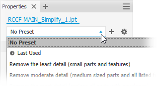
- Remove the least detail (small parts and features) - the settings are designed to remove small parts and features, resulting in the most detailed model.
- Remove moderate detail (medium sized parts and all listed features) - the settings are designed to remove a moderate amount of detail.
- Remove the most detail (replace top-level components with envelopes) - the settings are designed to remove the greatest amount of detail resulting in very basic shapes.
- No Simplification - the simplified version is full fidelity with respect to the assembly model. All details are visible in the model.
Tip: Select a preset close to what you want for detail, then use View Included and View Excluded to quickly select the remaining parts to expedite the process.The same method can be used for creating your own presets. For more information see To Work with Presets.
In the Input group, fields populate with the current state of the assembly. You can change them as needed.
 Model State. The active model state contains the components that define the envelope size. Changes in a model state affect the envelope size.
 View. The active design view displays. Changes in design views do not affect envelope size.
Click the
 Associative option to link the simplified model to the design view. The option is not available with the Master design view.Note: When Associative is selected, the Components group is not available as all component changes come from the design view.
 Position. Component position contributes to defining the envelope size. Changes in position view can affect the envelope size.
Replace with Envelopes provide the means to replace components with simple shapes. When you click on an option, preview shows the parts represented as envelopes.
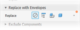
The replacement choices are:
 None - select this option when you are not using envelopes for the simplification. Components and Features groups are available for use.
 All in One Envelope - creates an envelope around the top-level assembly. The result is imprecise and useful for developing a "keep out" area for the design. When this option is selected the Components and Features groups are hidden.
 Each Top Level Component - creates an envelope around assembly first-level components. Component selection tools display. Feature selection tools are hidden.
 Each Part - creates envelopes for all parts in the assembly. Feature selection tools are hidden.
When any of the replacement choices are selected, you can specify the Type:
- Orthogonal Bounding Box - creates the envelope in form of orthogonal bounding box.
- Oriented Minimum Bounding Box - creates the envelope in form of oriented bounding box.
- Oriented Minimum Bounding Cylinder - creates the envelope in form of oriented bounding cylinder.
Tip: Combine the use of Presets, Replace with Envelopes, Exclude Components, and Remove Features to refine the simplified model you want to output.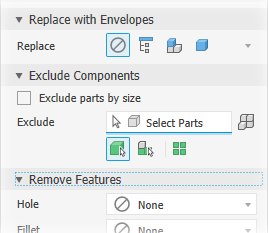
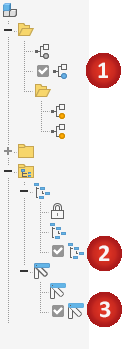
Exclude Components - provides options for selecting components to include in or exclude from the simplified part. Select individual components or all occurrences of a component.
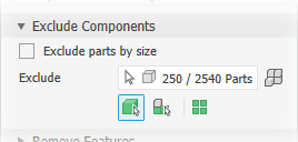
Remove parts by selection (default). Remove parts by size is deselected and the Exclude selector is active.
- Click the selection priority you want to use. Choose either
 Part Priority or
  Component Priority.
 - To select all occurrences of the selected item click the
 All Occurrences option.
 - Begin selecting parts or components in the canvas. An active selector has a blue highlight at the bottom of the control.
- Click the selection priority you want to use. Choose either
Remove parts by size
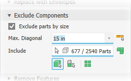
Select the Remove part by size option.
- Specify the maximum diagonal value for a bounding box. Parts or components that fit inside the bounding box are removed. Use one of these methods to specify the size:
- Enter the value in the Max. Diagonal edit field.
- Click the arrow at the end of the value field to select a recently used value.
- Click the measure diagonal bounding box button
 then select a part/component to supply the diagonal value.
- Specify the maximum diagonal value for a bounding box. Parts or components that fit inside the bounding box are removed. Use one of these methods to specify the size:
Click the selection priority you want to use. Choose from
-  Part Priority -  Component Priority To select all occurrences of the selected item click the  **All Occurrences** option.- Auto-detect locates and highlights the components.
- Continue selecting remaining components as needed to exclude them from the simplified part.
Click
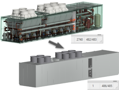
 View Excluded to see the components that will not participate in the simplified model or
  View Included to see the components participating in the simplified model. When you view in either mode, the numbers displayed in the edit field are relative to the label.
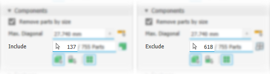 Note: Parts excluded explicitly are highlighted when you view Excluded. Parts excluded by size are not highlighted. Viewing options also work with envelopes.
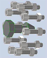
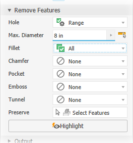
Remove Features provides options for selecting features by type and size to include in or exclude from the simplified part. The list of features include holes, fillets, chamfers, pockets (subtractive), embosses (additive), and tunnels (single and multiple entry). Internal voids are automatically removed.
Pocket recognizes subtractive features such as extrudes, revolves, sweeps, and so on.
Emboss recognizes additive or positive protrusions of various feature types.
Tunnel recognizes a set of faces contained inside the model that define an open area, having one or more entrances to the area from exterior faces.
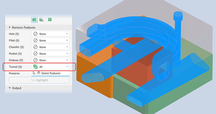
For each of the listed feature types specify which you want to remove and the way you want to remove them:
- None (default) - no features of this type are removed.
 All - all features of this type are removed.
 Range - all features equal to or smaller than the specified parameter are removed. Specify the value that defines the maximum size to remove.
Preserve - click the selector and select the features you want to retain from those being removed.
Note: The rules for feature recognition are minimal allowing for crossover, for example, holes also meet the definition for tunnels. Thus, some holes outside of a range may be removed as Tunnels. To resolve this, you can click Preserve and select any feature you want to remain in the simplified part. Highlight applies a color to the features to be removed.
Output provides options to define the output type and structure for your intended use.
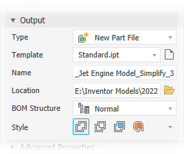
Type - three output choices are provided:
New Part File outputs an Inventor part based on the selected template.
Substitute outputs a simplified Inventor part that populates a Substitute Model State.
Note: When the active model state is a substitute, the Simplify command is not available.Note: In the BIM Content environment, Substitute is the only Output Type available.Revit Model (RVT) outputs your Inventor design as a Revit model (RVT).
Model orientation: The export process looks at the Inventor ViewCube Top and the Inventor Y-axis. If the Y-axis is perpendicular to the Top plane, the model is rotated so the Inventor Z-axis is perpendicular to the View Cube Top plane.
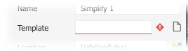
Template - sets the part template file to use for the new part file output. Choose between Sheet Metal or Standard part templates, or navigate to a custom template. If the template field is empty an alert will show next to the field.
Name - use the default file name or specify your own. The default uses the assembly name and adds a suffix.
Location - Sets the location of the new file. To find the part when the assembly is opened, specify its directory by a path in the project used for the assembly.
BOM Structure - Sets the BOM structure for the component, Normal is the default.
Note: You can override the structure to be Reference at the component instance level.Note: Not used for RVT output.Structure - used only for RVT output, choose the desired Structure option:
All in One Element - a Revit model with one element representing the simplified assembly is output.
Each Top Level Component - a Revit model with multiple elements representing the first level components of the simplified model.
Enable updating - creates a browser node that enables you to edit the simplification and update the exported RVT. This option is selected as a default. If deselected, no browser node is created and export criteria is not retained. Any updates to the exported file require exporting the model again.
Note: is advisable if the Inventor design is expected to change as the exported RVT file can be updated with changes without exporting again.
Style is used for IPT output, provides up to four choices.
Note: Not available for RVT output.Choose from:
 Single solid without seams
 Single solid with seams
 Maintain Each Solid
 Single composite
Advanced Properties provides other settings that help manage the simplify output. These are the general settings:
Break link to break link between the parent assembly and the simplified part.
Note: Not available for RVT output.Suppress link to suppress link between the parent assembly and the simplified part.
Note: Not available for RVT output and when the Break link box is checked.Rename simplified components. The following items are renamed:
The selected and all child browser nodes. The part renaming follows this pattern: "Part[sequence number]:[instance number]" which yields "Part1:1", "Part2:1", and so on. For part instances the instance number is iterated which yields "Part1:1", "Part1:2", and so on.
The elements under the Solid Bodies or Surface Bodies folders. The element renaming follows this pattern: Surface body nodes are renamed "Srf1", "Srf2", and so on, and Surface feature nodes are renamed "Surface1", "Surface2", and so on.
The Assembly node is renamed to Assembly1.
Note: Not available for RVT output.
Fill internal voids to fill all internal void shells in the simplified solid body part.
Remove internal parts selected by default. Inventor looks at the model from 14 standard directions (six orthographic and eight isometric) to determine a parts visibility state. Parts deemed not visible are removed.
Use Link face color from source component to link color from the source component into the target part. If deselected, the appearance is set to default appearance of the target part.
Make independent bodies on failed Boolean to create a multi-body part when a Boolean operation fails on one of the single solid body style options. Available only when Style is Single body with no visible edges between planar faces or Single body with visible edges between planar faces.
Note: It is possible to produce gaps when small faces are removed. If gaps are present, the result is a non-manifold body.Note: Not available for RVT output.Note: All internal voids are automatically filled.Use Create model parameters to create three read only parameters for the "Edge A", "Edge B", and "Edge C" are created in the simplified file parameters window.
Click OK to create the simplified part from the specified criteria.
To Edit a Simplify Substitute
Substitutes are model states based on a simplified model. They are added to the assembly and placed in the Model States Substitutes folder. To edit the simplified substitute:
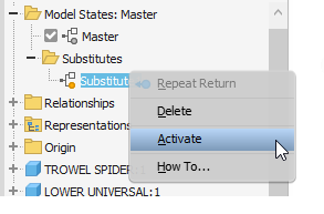
In the browser, expand the Model States
Substitutes folder.Right-click the Substitute you want to edit and click Activate. The model updates to display the substitute.
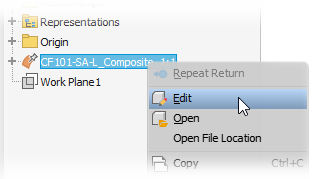
In the browser, right-click the substitute model and click Edit.
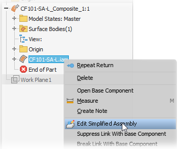
In the browser, right-click the and select Edit Simplified Assembly.
In the property panel, modify any of the following as needed:
- Initial State - select a different model state, design view, or position view
- Envelopes
- Components - include or exclude additional parts
- Features - add or refine the parameters for features being removed
- Output Style
Click OK. The substitute updates.
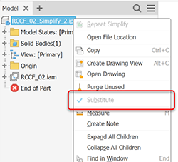
Easily Identify a Substitute or Simplified Assembly
Whenever a part or assembly is created to be a substitute component, the context menu for that component displays a read-only status called Substitute. When the Substitute is checked, the part or assembly is a substitute model. Therefore, all part files have the Substitute status. It is checked ONLY if the component was created as a substitute component.