To Work with Sketches
You can switch between sketch and construction geometry, redefine a sketch to a different plane, and in 2D sketches, you can measure region properties, slice, or add text or images.
Locate a Sketch in the Browser
Select any geometry in a part or assembly sketch, right-click, and choose Find in Browser.
The sketch of the selected geometry highlights in the browser.
Construction geometry constrains normal sketch geometry. It can be used in sketches that use parametric features; construction geometry isn’t used to define profiles or paths. Construction geometry does not add features when the sketch is consumed.
Switch Between Sketch and Construction Geometry
Geometry behavior in a sketch depends on the linetype assigned to it. Sketch geometry that uses the default, normal linetype can be consumed by features.
To manually invoke construction geometry:
- Before starting to draw in the sketch environment, click Sketch tab
 Format panel Construction.
 - In an active sketch, select the geometry and then click Construction to convert sketch geometry to construction geometry.
- Before starting to draw in the sketch environment, click Sketch tab
To turn off construction geometry, click Construction again.
Redefine a Sketch to a Different Plane
In a part or assembly file, you can move a sketch to a different plane. Redefining a sketch plane is useful if you need to reorient a feature on a part, or if you want to delete a feature but keep its sketch for use in another feature or a new face or work plane.
- Right-click the sketch in the browser and choose Redefine.
- Click the face or plane on which you want to attach the sketch.
Measure Region Properties (2D Sketches)
In an active sketch, click Inspect tab
Measure panel Region Properties  .
.In the graphics window, select one or more sketch loops.
In the Region Properties dialog box, click Calculate.
Inventor calculates the following measurements, depending on your selection:
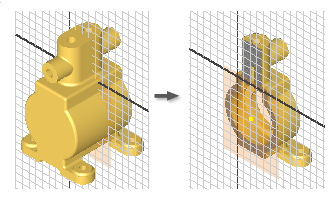
Slice Graphics (2D Sketches)
Sometimes geometry obscures your sketch plane, or components in a part model hide it. To reveal the sketch plane, you can temporarily slice away the obstructing components.
Rotate the model so that the portion you want to slice away faces you.
In the browser, double-click the 2D sketch you want to edit.
In the status bar, click Slice Graphics
 or press F7.
Inventor removes the portion of the model facing you, revealing the plane for the sketch geometry.
Use commands to create geometry on the sketch plane.
To restore sliced graphics, do one of the following:
- Click a feature command.
- Click the Finish Sketch
 to end the sketch.
 - Click Slice Graphics in the status bar.
- Press F7.
Add Text (2D Sketches)
You can add text, such as a model number, manufacturing date, or brand, to a sketch. The text will ultimately be stamped, etched, or engraved into the part. You can add text in a sketch, finish the sketch, and create the emboss feature, selecting the text as the profile.
In Inventor, you can add linear text or geometry-aligned text. Both types of text are like any other geometry: after you create it, you can double-click it to edit it, drag to move it, or select it and press Delete to remove it.
To add linear text to an active 2D sketch, click Text
 in the Create panel of the ribbon. Then, do the following:
In the graphics window, click to place the insertion point for the text, or click and drag to define a text box.
In the top of the Format Text dialog box, select a font, style, and text attributes.
In the middle of the Format text dialog box, specify model, drawing, and custom properties:
- Type. Specifies property and parameter types from the drawing, the source model, or the custom property source file (for external and model custom properties) specified in either the model or on the Drawings tab of the Document Settings dialog box.
- Source. Lists the available sources for the properties and parameters associated with the selected Type. Select the origin of the properties or parameters you will use.
- Property. Specifies a property associated with the selected Type. Available when creating or editing model or drawing text. In drawings, include text properties in notes, leader text, sketch text, symbol text, title block, and border text.
- Parameter. Specifies the parameter, associated with the selected Type and Source, to insert into the text. Click the arrow and select from the list.
- Precision. Specifies the precision for numerical properties displayed in the text. Select the desired precision from the list.
Note: The options available depend on the type of sketch: Model, Sheet, Draft View, or View sketch.Do any or all of the following:
- Type text in the gray text area at the bottom of the Format Text dialog box.
- Click Add
 to insert the selected property or parameter in the text. Available when creating or editing model or drawing text, including sketch text, symbol text, note text, leader text, title block, and border text. Not available for Prompted Entry type.
Click OK to accept the text and close the dialog box.
To add geometry-aligned text to an active 2D sketch, click Geometry Text in the Create panel of the ribbon. Then, do the following:
- In the graphics window, select the line, art, or circle to which you want to align the text.
- In Geometry-Text dialog box, specify the Direction, Position, Start Angle, Offset Distance, and other options. Click Launch Text Editor
 to open the Format Text dialog box to access iProperties and parameters. When you click OK in the Format Text dialog box, your selection is added to the Geometry-Text dialog box.
 - Click Update to preview the text in the sketch.
- Click OK to accept the text and close the dialog box.
Add Images (2D Sketches)
You can place artwork in parts to represent application of decals, painting, or silk screening. After you place an image in a sketch, use Decal and Emboss to achieve effects such as raised text, imprints, or silk screens. These commands can also conform the image to an irregular shape or surface.
Inventor sketches can include .BMP, .GIF, .JPG, and .PNG images as well as Excel workbooks and Word documents.
In a 2D sketch, select a planar face or work plane and then click Image
 on the Insert panel of the ribbon.
Navigate to the folder that contains the image file and then click Open.
Tip: Select the Link option so that changes made to the image file can be reflected in Inventor.Click in the graphics window to place the image. The cursor attaches to the upper-left corner of the image.
Click to place additional images, or right-click and choose OK.
After the image is placed, you can:
Drag from the center to reposition the image.
Click a corner to rotate the image.
Click an edge to resize the image (aspect ratio is preserved).
If the image file is linked, right-click it in the browser and choose Update to retrieve the latest version of the file.
Right-click the image and deselect Visibility to temporarily hide the image in the sketch. The bounding box remains visible.
Right-click the image in the browser and choose Delete to remove it from the sketch.
Access the Image Properties dialog box: Right-click the image and choose Properties. Here you select to render the image with unchanged alpha values (Alpha transparency) and specify a transparency color.
- Change its orientation (parts only).
- Use Mask: Select to make chroma key image pixels transparent. This option ignores any existing image alpha layer.
- Set Chroma Key: Select to specify a transparency color.
- Use Image Alpha (only available if the image supports alpha layer): Combines the background with the image using the alpha layer of this image.