Directly homogenize lattice components and support structures in Netfabb Simulation.
Video length (6:05).
Sample files for use with the tutorials are available from the Downloads page. Expand the downloaded ZIP archive into a convenient directory from which you can import files into Local Simulation as you need them.
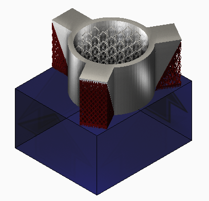
In this exercise, we demonstrate how to homogenize lattice type components and support structures directly from Netfabb Simulation. Homogenization is the process of representing a periodic type structure with a volumetric representation. As the finite element mesh is driven by the smallest feature that needs to be represented, homogenization allows the use of much larger elements for regions of fine support structure or component lattice. This results in much shorter simulation times and reduced RAM usage. Consult the Homogenization page for additional information on this topic.
- In Local Simulation, start a new simulation, browse to your saved Example files folder, and from the Example_22 folder, import SpokedCylinder.stl.
- In the
Import dialog, check that the settings are as shown below:
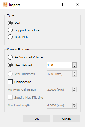
Note that Volume Fraction is set to 1.00 and Homogenize is not selected as this part is fully dense. We will use different settings in this dialog as we import Support Structures and a Lattice component from the Example_22 folder.
- Import the part file Lattice.stl, set the Volume Fraction to As Imported Volume and select Homogenize. These settings will create a volumetric 'shrink wrap' of the Lattice component using a Volume Fraction calculated from the volume of the imported STL file.
- Import Support1_Solid.stl, set Type to Support Structure, Volume Fraction to User Defined 0.22, and select Homogenize. This represents the case when you have pre-calculated the Volume Fraction or are investigating support structure density using the simulation.
- Import Support2_0Thickness_Loose.stl, set Type to Support Structure, select Homogenize, and set Volume Fraction to Wall Thickness of 0.22 mm. This case corresponds to the common occurrence when you do not know the volume or volume fraction of a zero-thickness lattice type support, so you choose this setting to calculate this based upon the support structure wall thickness.
- Import Support3_0Thickness _Fine.stl, set Type to Support Structure, select Homogenize, and set Volume Fraction to Wall Thickness of 0.15 mm. These settings are chosen to show that a variety of support designs may be applied to different support STLs.
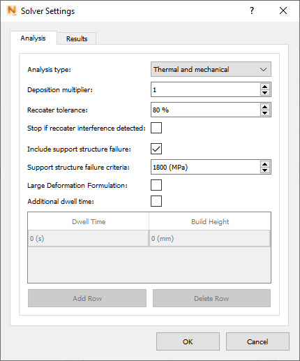
- On the Home tab, open Solver Settings.
- On the Analysis tab, select
Include support structure failure, and set
Support structure failure criteria to
1800 MPa.
- Click
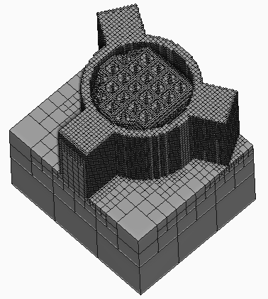
Mesh Preview to generate a mesh for all parts and supports.
Note the dimpled top of the lattice part mesh inside the hole of the spoked cylinder.
- To view the mesh in more detail, go to the
View tab and click
Clipping
 . In the
Edit Clipping Plane dialog, select
Snap to YZ to orient the plane, and use the
Distance along normal slider to move the plane along the X axis. If you want to slide the plane along the Y axis, select Snap to ZX.
. In the
Edit Clipping Plane dialog, select
Snap to YZ to orient the plane, and use the
Distance along normal slider to move the plane along the X axis. If you want to slide the plane along the Y axis, select Snap to ZX.
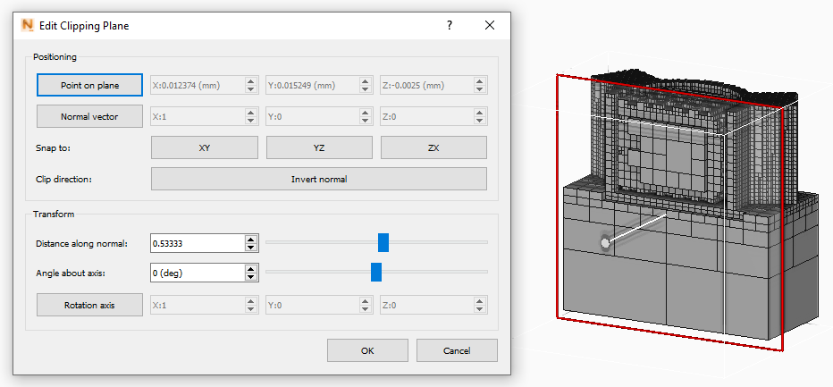
The irregular mesh is created because the gaps in the lattice are too large to be spanned by the default Maximum Cell Radius. The Maximum Cell Radius sets the largest gap or feature that will be filled in during Homogenization. By default, this value is 2.50 mm, meaning that lattice holes up to 5.00 mm across will be homogenized. However the features of the Lattice component in this example obviously exceed 5.00 mm. We can improve the lattice mesh by increasing the maximum cell radius setting.
- To restore the full mesh, close the Edit Clipping Plane dialog.
- In the Browser, right-click
.

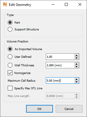
- In the Edit Geometry dialog, select
Homogenize, change
Maximum Cell Radius to
5.00 mm, and click
OK.
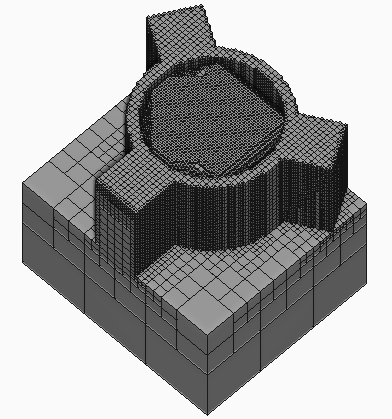
- On the Home tab, click
Mesh Preview to regenerate the mesh. You should notice that the lattice mesh is much smoother.
- Click
Solve to run the simulation.
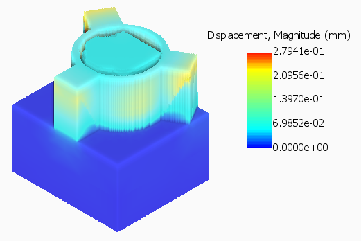
The Displacement results show that the different densities of support structures affects the part scale distortion of these parts. You can use this data to optimize support design, which can be done much more rapidly than if all the supports were modeled directly with very fine meshes.
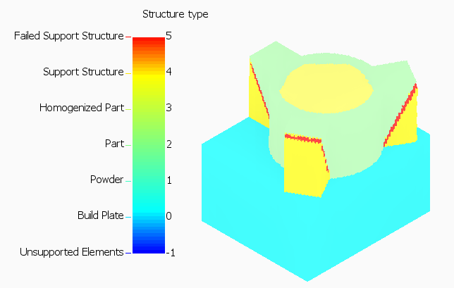
The Structure Type results show severe support structure failure. This indicates that the supports are likely too weak and should be made more dense.
- Finally, if you examine the mechanical log file, you will see critical warnings indicating both support structure failure and recoater blade interference, which should be taken into account when approaching the redesign of this component and its supports.