Non-Homogenized versus Homogenized support structures
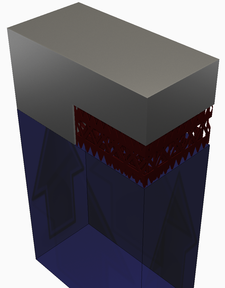
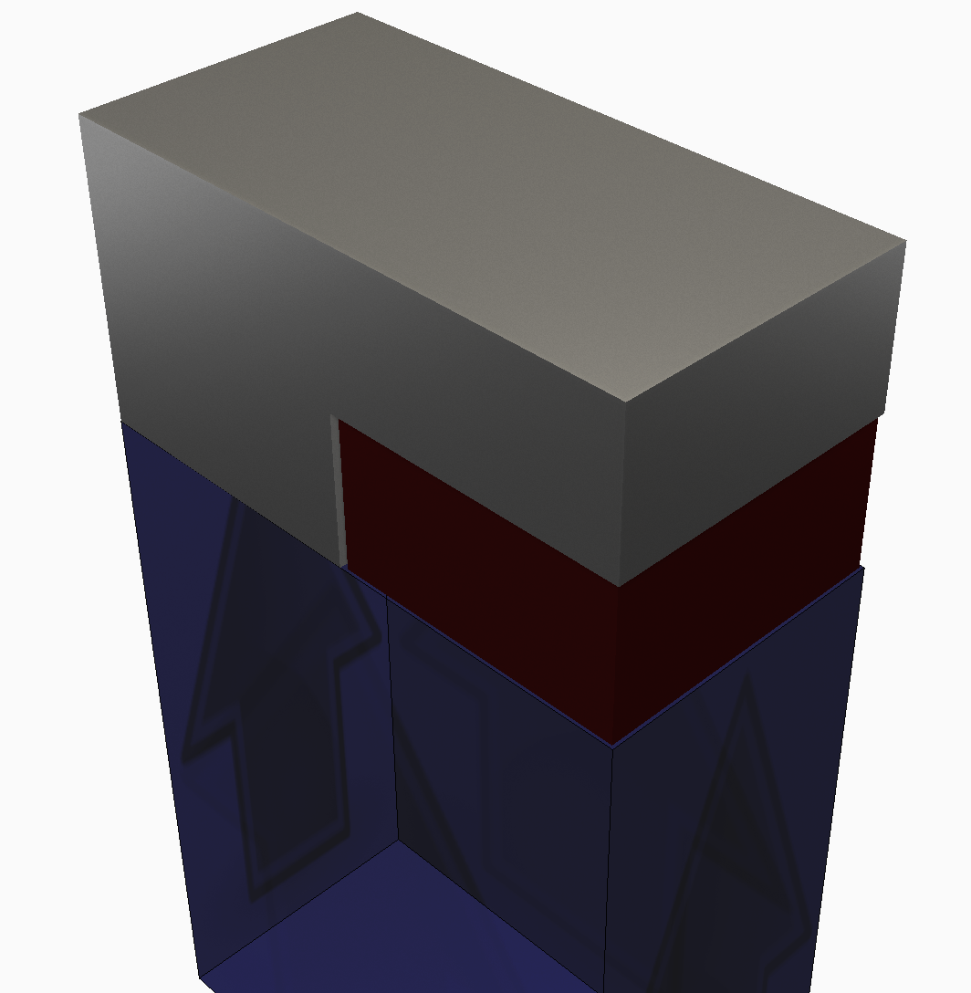
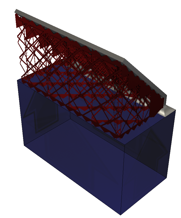
As shown below, while a fine, lattice type support structure with a thickness can be meshed and run, it is recommended that users implement the homogenization technique to reduce memory usage and simulation time. By default, upon import, support structures are colored red.
|
|
| Non homogenized support structure | Homogenized support structure |
| Has material thickness | Has material thickness |
| Meshable | Meshable |
| Requires very fine mesh settings | Can use very coarse mesh settings |
| High memory consumption | Low memory consumption |
| Slower simulation | Faster simulation |
Homogenization upon import
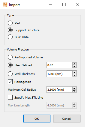
The Import dialog includes several controls for homogenization of parts and support structures.
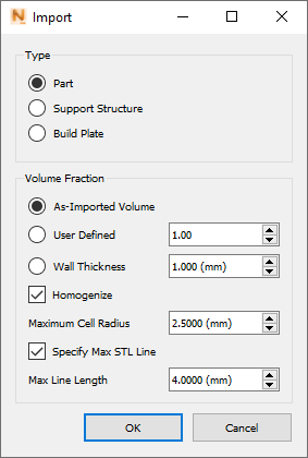
After you select the object Type and check the Homogenize box, you can choose how to define the Volume Fraction of the part or support:
- As-Imported Volume calculates the volume fraction from the volume of the imported STL file.
- User Defined allows you to specify a numeric value for volume fraction. 1.00 indicates a fully dense object, so values are usually set lower than this to indicate the proportion of solid material in the original object. For example, a value of 0.3 indicates that 30% of the object volume is solid.
- Wall Thickness allows you to specify a value for the thickness of structural members that form the part or support.
Maximum Cell Radius is usually left at the default value of 2.50 mm, as this value can fill in lattice holes up to 5.00 mm in diameter. If a lattice has larger holes, then maximum cell radius should be increased.
Specify Max STL Line is used to set a shorter maximum line length in the STL for the purpose of filling gaps during homogenization.
Manual homogenization of support structures
To homogenize a support structure
- Create the supports, as built, using the material thickness of the support walls to ensure the ensuing STL or CAD file has a volume.
- Determine the volume of the original support structure. If the part has been imported into
Local Simulation, this can be found by navigating to the file tree, right clicking on the part and choosing
Diagnostics from the drop-down menu. If there are multiple parts imported, select the tab corresponding to the correct part.

- Recreate the support structure but as a volumetric support structure, so that the support is a solid volume which occupies the same bounds as the original support.
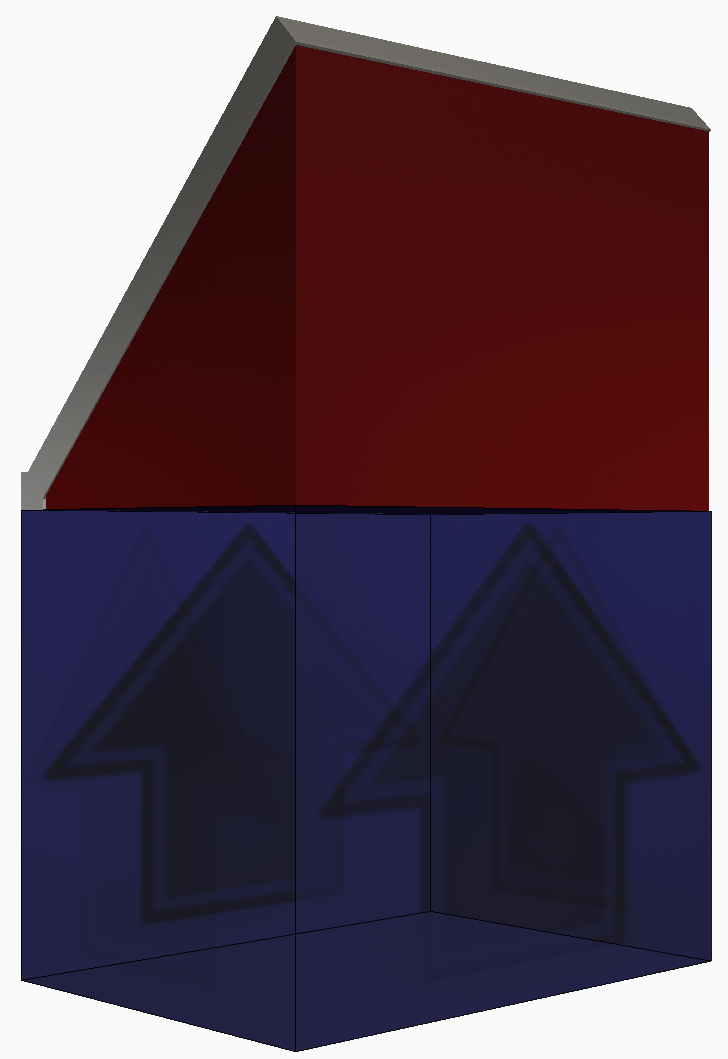
- Determine the volume of the volumetric support structure.
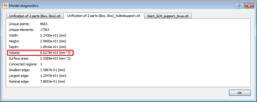
- Calculate the volume fraction: Volume fraction = Volume of original support structure/Volume of volumetric support. For this example the original volume is 102 mm³ and the homogenized support is 6630 mm³, which yields a volume fraction 0.0154.
- Import the volumetric support structure in
Local Simulation and when prompted, enter in the calculated volume fraction, rounded to the nearest hundredth.
When the Homogenize box is checked, you can optionally set a Wall Thickness value as an alternative to a User Defined Volume Fraction. Changing the Maximum Cell Radius value is not recommended unless you are working with a lattice that has very large gaps, as described in the next section.
How to set maximum cell radius
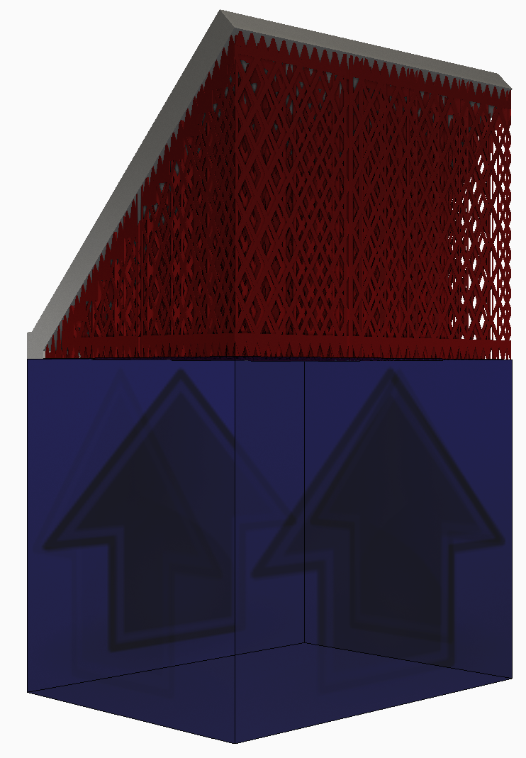
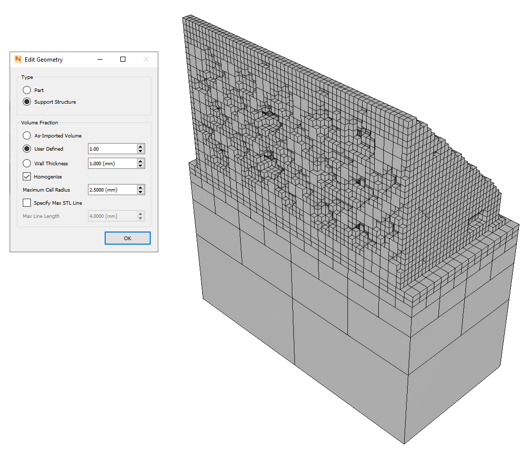
The following figure shows a support structure with large gaps in the lattice.
These gaps indicate a large cell radius in the structure. When this support structure is meshed using the default 2.50 mm maximum cell radius, the resulting mesh is not fully homogenized, as the lattice cells are too large to be filled in by the mesh elements:
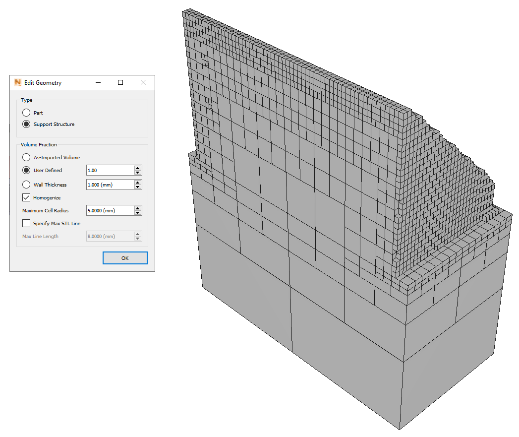
In the Browser, right-click the support structure and select Edit Geometry. Increasing the maximum cell radius to 5.00 mm and remeshing yields a much more completely homogenized support structure, as the large gaps are filled in with larger mesh elements. This setting will produce a faster and more accurate simulation result.
If the model has holes in either the part or support structures, as demonstrated in Tutorial 10, you may need to adjust the maximum cell radius to fill gaps in the lattice but not fill the holes.