In Netfabb, generate supports for use in Local Simulation.
Video length (5:00).
In this tutorial, the concept of homogenization of support structures is shown, and it is demonstrated how to use Netfabb and Local Simulation together for the efficient modeling of support structures.
Sample files for use with the tutorials are available from the Downloads page. Expand the downloaded ZIP archive into a convenient directory from which you can import files into Local Simulation as you need them.
Homogenization
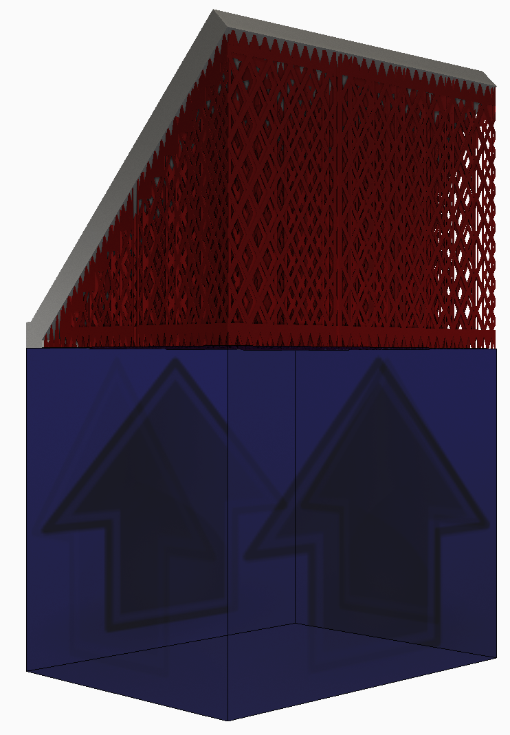
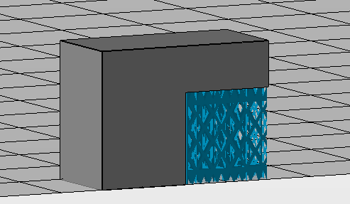
The first figure below shows lattice support structures. The volume fraction is small, meaning that only a small portion of the total volume of the support region is occupied by solid material. Meshing a fine lattice adds a significant number of small elements and thus degrees of freedom, which extends the run time of the simulation and increases the required memory usage.
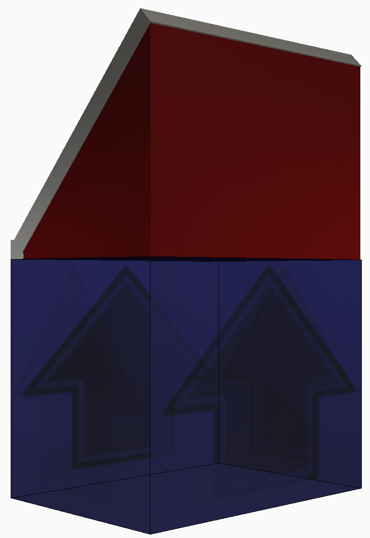
To improve modeling efficiency, users are advised to always implement support structure homogenization. Homogenization uses a volumetric type support structure that fills the same volume as the support that will be printed. The volumetric support can be coarsely meshed which reduces both memory consumption and computational times. To ensure the homogenized structure will exhibit the same thermo-mechanical behavior, the material properties of the homogenized structure are scaled by the volume fraction of the nominal support structure. Consult the Documents topic for further details about the homogenization process and how to manually calculate volume fractions for support structures generated outside of Netfabb.
To generate the supports in Netfabb
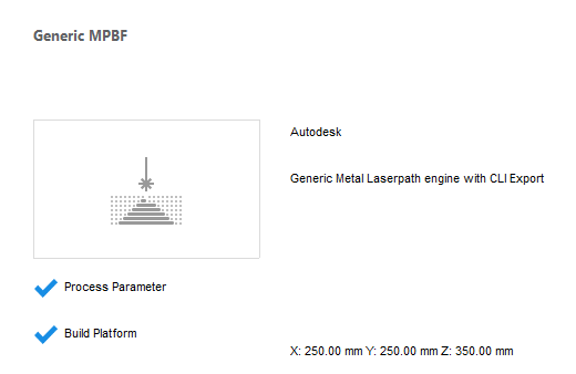
- Launch Netfabb, and if you see the My Machines dialog open, showing the Generic MPBF machine, right-click the machine image and select Open Machine. Skip to Step 5 below.
- To select a machine, first click
 .
.
- If it's not already there, add
Generic MPBF to your list of machines.
- In the My Machines dialog, click the Add Machine button.
- In the
Select a machine to add dialog, scroll down the
Process Parameters list, expand the
Autodesk category, and click
Generic MPBF.

- Click the Add to My Machines button at the bottom of the dialog.
- In the
My Machines dialog, with the machine selected in the left pane, click
Open.
You should see Generic MPBF selected at the top of the project model tree.
- Right-click and add the sample file Example_15.stl .
- In the right pane, note the check box for
Distance between Part and Platform.
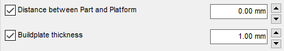
In the field to the right, set the distance to 0.00 mm and press Enter. The part must be seated directly on the platform for proper creation of support structures.
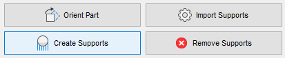
- Click
Create Supports.
- At the bottom of the window, click
Run Support Script, select
SLM, and click
Execute.
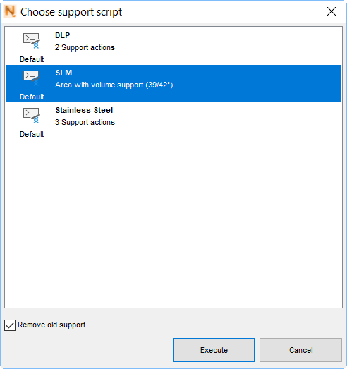
The lattice-like supports are created.
- Click Apply support; in the Editor Apply Behavior dialog, click Keep Editor.
- Click Start build simulation; in the dialog that opens, enter a suitable file path and name, such as Example 15, leaving in place the file extension .3mf. Click Save.
- In the
Start build simulation dialog, ensure that
Postprocess-repair support volumes for simulation is checked, select the
Local Simulation version, if both are available, and click
Simulate.
The exported file takes a minute or so to generate, then opens inside the Local Simulation window on a large build plate. Note that the lattice support has been replaced with a solid block.
To modify the support in Local Simulation
- On the Home tab, click .
- To resize the build plate, click the Snap to X and Y button, then click OK.
- In the Browser, right-click on the support structure, which has a name that includes
_hulledsupport_, select
Edit Geometry, and in the dialog, you see that
User Defined is selected by default.
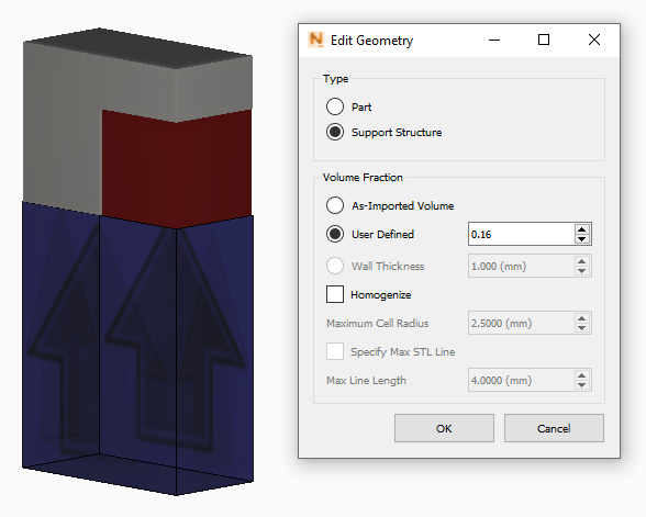
Note that the Volume Fraction brought over from Netfabb was automatically calculated at 16%. Click OK. Next, generate a mesh preview to see the results of homogenization.
- On the Home tab, click
Mesh Preview and save the project in a suitable location.
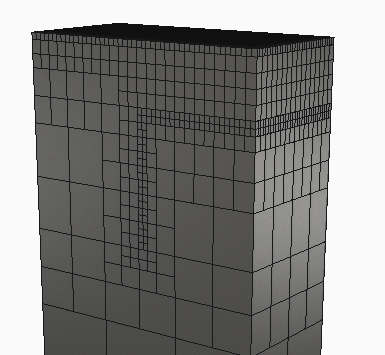
Upon viewing the results observe that coarse mesh elements are used where the part and support are near the build plate, and fine elements along the interfaces between the part and support. This part will simulate in a much shorter time than if the original lattice like supports had been used, while attaining the same predictions of thermo-mechanical behavior during processing.