Activating LC, moving parts and bodies into and out of it, and importing and exporting components
Jump to:
- To activate Lattice Commander
- To transfer parts into Lattice Commander
- To transfer bodies out of Lattice Commander
- To generate a mesh part from a component
- To export and import components
To activate Lattice Commander
From the menu, choose
Modify >  Lattice Commander. This creates a new branch in the
project tree called
Lattice Commander. This creates a new branch in the
project tree called
 Lattice Commander, if it isn't there already. If it does exist,
Netfabb switches to it. If you have a part selected while using this menu option, this part is automatically loaded into a mesh body of a new component.
Lattice Commander, if it isn't there already. If it does exist,
Netfabb switches to it. If you have a part selected while using this menu option, this part is automatically loaded into a mesh body of a new component.
 Lattices entry in the
project tree and then click
Lattice Commander in the
context view.
Lattices entry in the
project tree and then click
Lattice Commander in the
context view.
To transfer parts into Lattice Commander
When you add a part into
Lattice Commander, it is always added into a
 component, an independent working set of bodies. This may be a new
component that
Netfabb automatically creates, or an existing
component.
component, an independent working set of bodies. This may be a new
component that
Netfabb automatically creates, or an existing
component.
To create an empty component
- In the
project tree, click
Lattice Commander to select it.
- Then, from the main menu, choose
Component >
 Add Component.
To add to a new component
- In the
project tree, click and drag the part from
 Parts or a machine workspace.
- Drop it onto the
Lattice Commander entry.
To add to an existing component
- In the
project tree, click and drag the part from
Parts or a machine workspace.
- Drop it onto the entry of a
component.
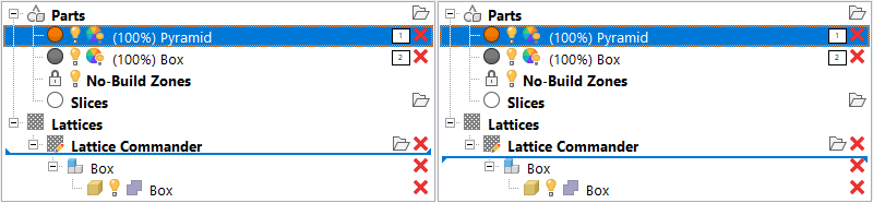
The tips of the blue line indicate how Helix is added into Lattice Commander. Left: Into a new component. Right: Into the existing component named Box.
To transfer bodies out of Lattice Commander
- You can drag any
 mesh body from
Lattice Commander directly to a regular platform.
Note: You cannot
mesh body from
Lattice Commander directly to a regular platform.
Note: You cannot lattices or
 skins this way. To create mesh information from skins and lattices, you must go through
 Generate Component. Also, it is not possible to move mesh bodies directly to
 Slices or machine workspaces. Move them to the default platform named
Parts first.
Slices or machine workspaces. Move them to the default platform named
Parts first.
- You can also use a lattice to generate bar supports without needing to generate a mesh from the lattice first.
- Click and drag the
lattice body from the
Lattice Commander section to the
 Generate Support section of the part to be supported with the generated lattice.
- Click and drag the
To generate a mesh part from a component
You can convert an entire component into a part. Using the
roles you can set for each of the bodies in a component,
Netfabb assembles them into the result. The benefit of this method is that you do not need to generate the mesh information manually. The entire mesh generation and assembly is handled automatically, producing only the final part and putting it onto the platform that was selected last before clicking
Generate Component.
- In the project tree, select the
component.
- Adjust the role of each body as necessary by clicking on the role icon, cycling through
 Solid,
 Trim,
Trim,
 Void, and
 Ignore.
- Select the mesh generation method:
- Generate part mesh creates regular-shaped triangles of uniform size. Forms neater junctions and follows rounded surfaces best, but creates small triangles even on completely flat areas, resulting in rather high triangle counts.
- Generate part mesh (legacy) uses an older meshing algorithm. It generates larger triangles and observes hard edges best, but also creates rather large beam junctions.
- Generate part for FEA generates the volumetric, linear tetrahedral mesh and directly writes the NAS file suitable for finite-element analysis. Using this option requests a file name for the NAS file to write.
- In the main menu, click
Generate.
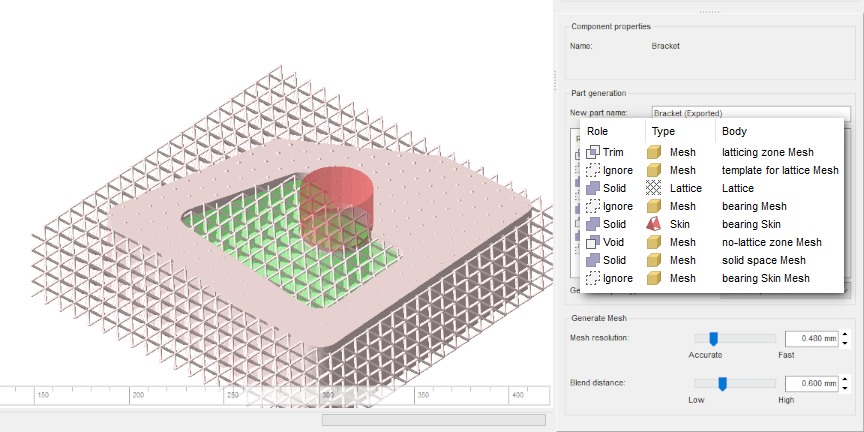
A component being previewed, with all the available roles in use. Trim volumes are shown in green, void volumes in red. Solid bodies appear in pale pink, ignored ones are hidden.
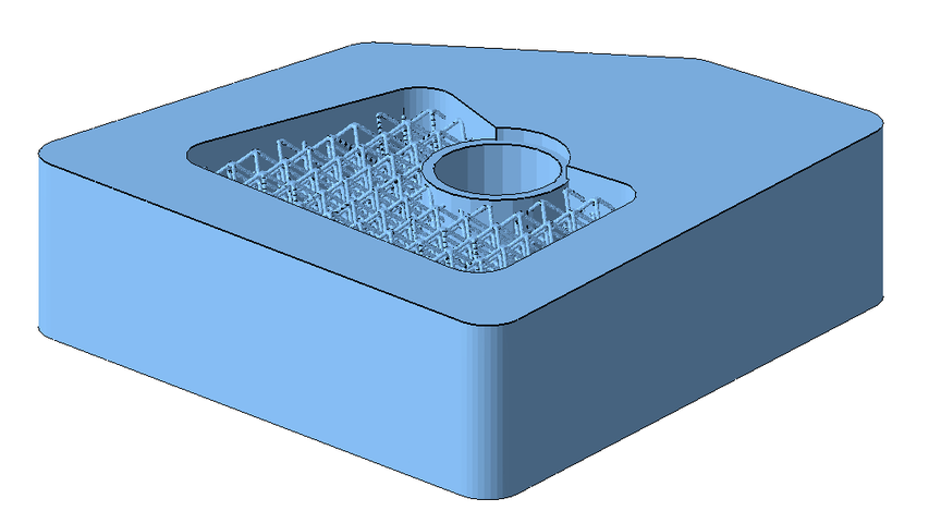
The result of generating a part from the example above.
To export and import components
You can save and load components in the form of 3MF files. This stores meshes, lattices, and skins. However, visibility and roles are not stored.
Import 3MF Component
- In the project tree, click on any node of
Lattice Commander.
- In the main menu, click
 Import component.
- In the Open File dialog, navigate to the 3MF file to load, select it, and click Open.
Export 3MF Component
- In the project tree, select any
body of the component to export, or select the
component itself.
- In the main menu, click
 Export component.
- In the Save File as dialog, navigate to the location where to save the 3MF file, then click Save.
Using the same dialog, components also export to CSV, writing nodes in the format of <ElementID>;NODE;<X>;<Y>;<Z> and beams as <ElementID>;BEAM;<NodeID1>;<NodeID2>;<Radius1>;<Radius2>.
Example:
1;NODE;0.0000;0.0000;0.0000
2;NODE;50.0000;0.0000;0.0000
3;NODE;50.0000;50.0000;0.0000
4;NODE;0.0000;50.0000;0.0000
5;NODE;0.0000;0.0000;50.0000
6;NODE;50.0000;0.0000;50.0000
7;NODE;50.0000;50.0000;50.0000
8;NODE;0.0000;50.0000;50.0000
9;BEAM;3;4;0.8660;0.8660
10;BEAM;2;4;0.8660;0.8660
11;BEAM;1;4;0.8660;0.8660
12;BEAM;2;3;0.8660;0.8660
13;BEAM;1;2;0.8660;0.8660
14;BEAM;1;6;0.8660;0.8660
15;BEAM;2;6;0.8660;0.8660
16;BEAM;5;6;0.8660;0.8660
17;BEAM;2;7;0.8660;0.8660
18;BEAM;3;7;0.8660;0.8660
19;BEAM;6;7;0.8660;0.8660
20;BEAM;5;7;0.8660;0.8660
21;BEAM;3;8;0.8660;0.8660
22;BEAM;4;8;0.8660;0.8660
23;BEAM;5;8;0.8660;0.8660
24;BEAM;7;8;0.8660;0.8660
25;BEAM;4;5;0.8660;0.8660
Top