Apply multiple ring-shaped, concentric volume supports on a radial turbine or pump stator
Jump to:
- Overview
- Loading, arranging, and orienting
- Analyzing supportable geometry visually
- Continuing the analysis with measurements
- Continuing the analysis in the support editor
- Finalizing the support script
- Conclusion
Overview
A radial turbine or pump stator is a good demonstrator for how to approach supporting a part with multiple overlapping and concentric areas. A default, catch-all volume support would technically suffice, but would also be unnecessarily difficult to remove.
General approach
- Determine available clusters
- Set up support actions dedicated to the available clusters
- Adjust angles to reduce the amount of part surface unnecessarily
Loading, arranging, and orienting
- Load the demonstration part stator v1.step.
- Orient its circular faces parallel with the build platform and arrange it well away from the platform borders to give the supports you are about to generate some room.
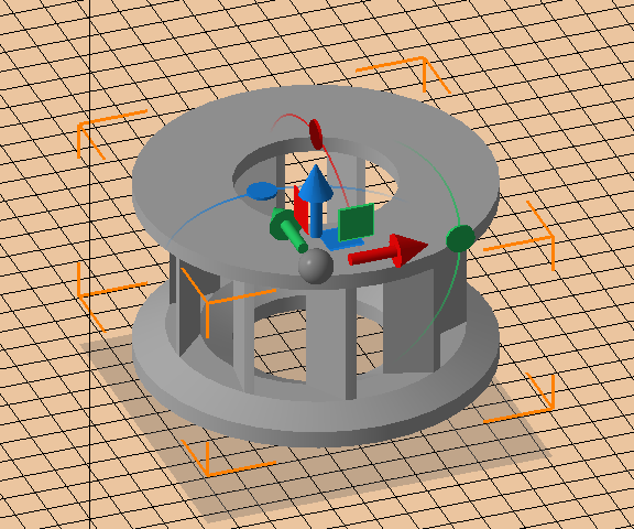
The stator demo part in the buildroom, with some leeway around and below it
Analyzing supportable geometry visually
To get a general idea of the available clusters, areas formed by contiguous triangles requiring support, this tutorial makes use of two main tools: Measurements and support generation.
Using clip planes
- With the part oriented and arranged on the platform, move the Y slider in the Clip planes view until the line representing the plane crosses the part about half-way.
- Click the left part of the
 visibility icon to toggle the negative-Y-facing section.
- Click the FRONT face of the viewcube to switch to the perspective looking directly in positive Y direction.
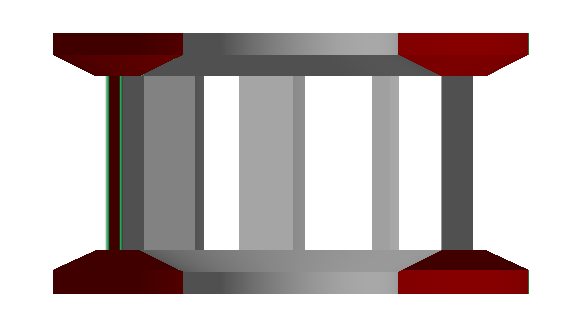
A look directly at the cross section of the part reveals angled inner and outer flanges and a level center track holding the vanes.
Continuing the analysis with measurements
- From the main menu, choose .
- In the context view, choose
 Surface >
  Angle Surface-XY Plane.
- In the 3D view, move the mouse pointer over the angled surface of the outer flange of the upper ring. This already highlights the respective triangle, plane reference, angle measurement, and numerical readout.
Note: Even though the part is still in CAD format, Netfabb triangulates its surface for its functions. As such, select a representative triangle for the measurement as there is no way to average a surface measurement across multiple triangles available.Tip: Hold the right mouse button and drag the mouse to vary the view before deciding which triangle to measure against.
- Click once to select the triangle.
- At this point, Netfabb may not have given you the best arc for your measurement of the downskin angle. Choose a suitable arc by moving the mouse pointer around the angle's apex, marked by the yellow bubble. Once you have found the desired arc, click once more to select it and finalize this angle measurement.
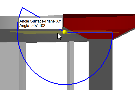
Move the mouse around the angle apex to select the desired arc.
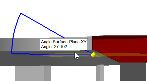
Now the downskin angle can be read off directly. Click to finalize the angle measurement.
Repeating the same angle measurement steps for the outer flange reveals that they are effectively equal. This means that the value of the angle alone cannot be used to distinguish between the inner and outer flange, only between flanges and the flat portion of the downskin. As such, another property is required, and for this we use the surface area.
To measure surface area we use the support editor as we are only interested in downskins and since we need to create supports on clusters anyway. There is also a way to measure surface area in repair, but this is not part of this tutorial.
TopContinuing the analysis in the support editor
Creating a new support script and adding a support action
- With the part selected, choose
 Generate supports from the main menu.
- In the context view, switch to the Support scripts tab.
- Click
 New script and provide a name for the script. This tutorial will be referring to it by the name "annular support".
- From the actions dropdown, select Area with volume support and click Add.
- Click Save, then Execute.
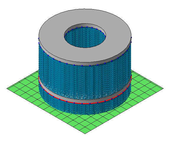
First-pass volume supports on the stator part
Identifying clusters, part 1
- With the first-pass volume supports generated, switch to the List tab in the context view.
- Expand the nodes of the tree view to see which clusters were generated and which support entities belong to them.
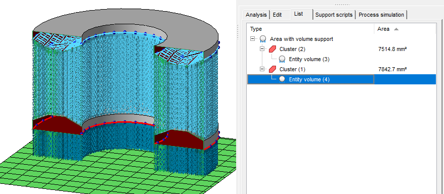
Selecting entries in this tree view highlights the respective clusters and entities in the 3D view. (The bracketed numbers are the respective element's identifier.)
In this first pass, the entire downskin is supported as a singular cluster. To differentiate between the sections and to force support generation into detecting them as separate clusters, the support script needs a more granular strategy.
Splitting the cluster
- Switch to the Support scripts tab and select the "annular support" script.
- Expand the Cluster section.
- Find the parameters Critical angle and Non-critical angle and adjust their values to me lower than the downskin angles of the flanges you measured before. For example, set them to 10° and 15°, respectively.
- Click
Save and
Execute.
The supports between the rings should now be confined to the center strips between the vanes only.
- Now add another Area with volume support action below the first one. Leave it at its default values and click Save and Execute again.
Identifying clusters, part 2
- Switch back to the List tab.
- Expand the nodes for the second Area with volume support entry.
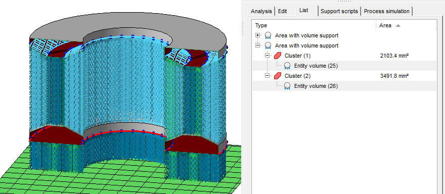
The area information for the respective clusters makes a separate, dedicated support actions for each of the flanges possible.
Finalizing the support script
With both the angles and the areas, enough information is available to treat each supportable surface separately.
Supporting the inner flange
- Switch to the Support scripts tab and select the "annular support" script.
- Select the second Area with volume support action and expand the Cluster node.
- Change the Maximum area to a value below the outer cluster's but above the inner cluster's area. For this tutorial, change it to 30 cm².
- Expand this action's Support properties node and change Stand angle to -20°.
Supporting the outer flange
- Add a third Area with volume support action and expand the Cluster node.
- Change the Minimum area to a value above the inner cluster's but below the outer cluster's area. For this tutorial, change it to 30 cm².
- Expand this action's Support properties node and change Stand angle to 20°.
With these adjustments done, click Save and Execute one more time.
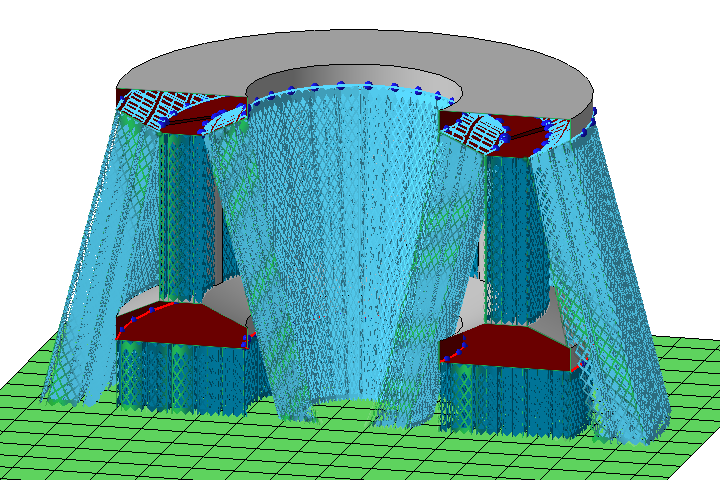
This stator can now be supported automatically by running a single support script.
Conclusion
In this tutorial you used clip planes, angle measurement, and the cluster and entity list to identify supportable areas and created a support script with several targeted support actions.
Top